Thicks91
Well-known member
- Joined
- Jan 9, 2023
- Messages
- 149
Thanks man! Ballin on a budget hahaThis thing is bitchin!
Thanks man! Ballin on a budget hahaThis thing is bitchin!
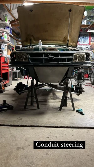
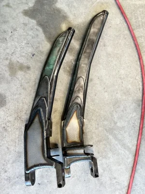
Sorry for the slow reply! It’s a threat motorsports kit. Makes shit easier, I made my own tie rods but the amount of time it would take to draw up a swinger and pitman arm set up didn’t add up. So I paid the man.Hey dude, where did you get your steering kit? Or did you make it? Thanks
Thanks for info. I was looking at that kit. Since it was basically complete. How did you determine the bends in the tierods?Sorry for the slow reply! It’s a threat motorsports kit. Makes shit easier, I made my own tie rods but the amount of time it would take to draw up a swinger and pitman arm set up didn’t add up. So I paid the man.
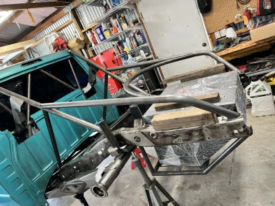
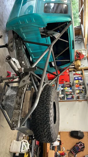
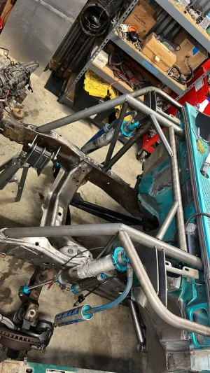
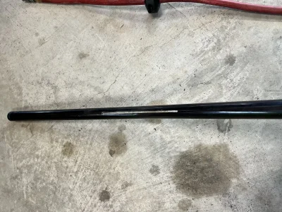
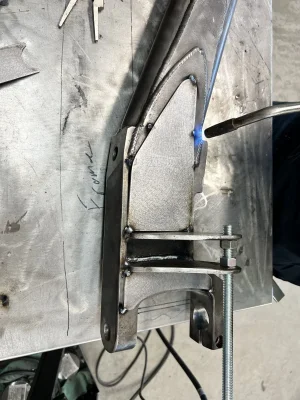
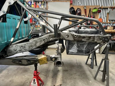
I started at ride height, I set the pit man arm to the swinger first and made sure that it was inline with the pivot. That’s your first step. So I put a piece of all thread in the pivot and through the swinger and that determined the where on the Frame I would tack for mock up. Has to be far enough forward that the link can be behind the swinger at full bump. Then I started with a piece of 1” EMT from Home Depot jacked up one beam and measures to the center of the frame to get the center of bend. started cycling the suspension at full bump and bending the tie rod as needed to clear the frame. Then I repeated that step on the passenger side and then once I got the bends down I checked the turning angle so that it doesn’t crash into the swinger and pitman arm at full lock. You might have to cut your tacks on the swinger and dial in how far forward it is. I’ll see if I have pics from when I was doing it.Thanks for info. I was looking at that kit. Since it was basically complete. How did you determine the bends in the tierods?
Thanks dude, progress looks rad.
I started at ride height, I set the pit man arm to the swinger first and made sure that it was inline with the pivot. That’s your first step. So I put a piece of all thread in the pivot and through the swinger and that determined the where on the Frame I would tack for mock up. Has to be far enough forward that the link can be behind the swinger at full bump. Then I started with a piece of 1” EMT from Home Depot and measured back from the tie rod 8” and started cycling the suspension at full bump and bending the tie rod as needed to clear the frame. Then I repeated that step on the passenger side and then once I got the bends down I checked the turning angle so that it doesn’t crash into the swinger and pitman arm at full lock. You might have to cut your tacks on the swinger and dial in how far forward it is. I’ll see if I have pics from when I was doing it.
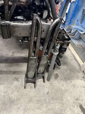
if you look back at some older pics of when I was doing the steering you will see the piece of all thread holding the swinger
Thanks man! I’m fortunate enough to have some good friends who show me the ropes. I’m no expert.That is infinitely helpful man.
Much appreciated. I think I tackle that.
Trucks looking great.