Local Legend Don't Call It An S10

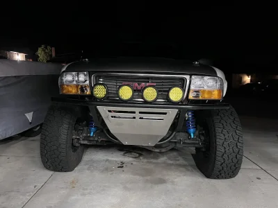
Thrashed on the truck after church today. Got the trans output seal replaced, tapped two bolt holes on the output from m10 to 7/16 since the old threads were nonexistent. Replaced the seal from the adapter to transfer case since I had it and the xcase was already off the truck. Got the transfer case back on, drive shaft installed, and added ATF. Topped off coolant as well. Then modified the new headlight housings to fit the new core support, new bulbs, connected all the grounds I was previously missing, and fired it up. Idled for about 10 mins before a couple laps around the neighborhood. Added more ATF to proper level, and another lap around the hood. For some reason it loads up on me when I get on the gas. I have a sneaking suspicion the grounds I used weren’t great, so I’ll try moving those tomorrow. But it also is showing codes for my knock sensors (they were supposed to be tuned out) and both o2 sensors (they’re brand new Bosch with less than 1000 miles, so not sure what’s up with that). Idk if either of those sensors will cause it to load up this badly, or if it’s just the block ground needing a better ground location.
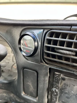
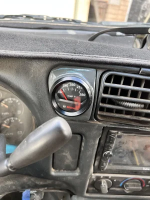
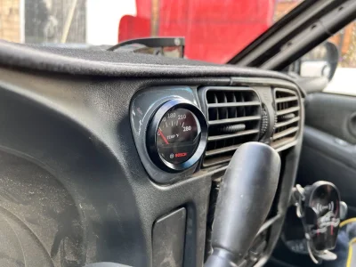
Last thing to do is connect the trans temp sensor.

We’ll get it figured out and hopefully go to Pismo this weekend!
 

Attachments

  • 12619FAF-44A6-4333-8673-280E948DD399.jpeg
    12619FAF-44A6-4333-8673-280E948DD399.jpeg
    251.3 KB · Views: 59
While dealing with all the other issues, I noticed a small miss at idle. I think I found the culprit.

1709746925033.jpeg

Is that bad?? hahaha. All the other plugs checked out fine. Replaced this one, along with new o2 sensors since they were coated in soot from tune issues. I've got the old ones cleaned off and will keep as spares. Hopefully meeting with my tuner tonight if the rain stops early.

1709746996967.jpeg
 
i applaud you for all the work you have put into this thing. Really impressed, wish i had that same drive.
 
3d scanned the 4x4 switch panel so I could print and mount my trans temp gauge. Turned out awesome. Hank (our new Dobie pup we rescued a few weeks ago) quickly got comfortable while I installed it
 

Attachments

  • 37BFFC45-59F8-4C99-B27F-2D4D88D0B4F0.jpeg
    37BFFC45-59F8-4C99-B27F-2D4D88D0B4F0.jpeg
    342.9 KB · Views: 30
  • 58BDF398-CE5D-45ED-8DB8-43932F9B4AE9.jpeg
    58BDF398-CE5D-45ED-8DB8-43932F9B4AE9.jpeg
    353.4 KB · Views: 34
  • DDF746E2-7FD8-4840-B5D2-26C5F3926CC0.jpeg
    DDF746E2-7FD8-4840-B5D2-26C5F3926CC0.jpeg
    292.9 KB · Views: 39
  • 3A47E4C2-871D-4365-8E7A-B59CAE0C42E8.jpeg
    3A47E4C2-871D-4365-8E7A-B59CAE0C42E8.jpeg
    426 KB · Views: 36
  • 1F1BF44D-C8EA-4F62-B2A3-F9E74731615C.jpeg
    1F1BF44D-C8EA-4F62-B2A3-F9E74731615C.jpeg
    422.5 KB · Views: 36
That mount come out great.

How did you build the form? I'm guessing there are some premade templates out there for gauges?
 
Have you looked into vapor smoothing? Pretty easy to build a rig

I remember hearing about it, but totally forgot about it. I'll have to do some research.

That mount come out great.

How did you build the form? I'm guessing there are some premade templates out there for gauges?

Thanks! I 3d scanned the old switch panel, made a model of it in my CAD program (going from points in space to a "solid" surface - much more challenging than I anticipated), measured out all the features I needed from my gauge to make it fit, and then 3d printed the form.

Here's some pictures from a failed modeling attempt I had done. It's all a continuously curved surface of varying radii, so no flat surfaces to really work from.
1711992217855.jpeg
1711992230288.jpeg
1711992239660.jpeg
 
How did you mount the sliders and the tent to the sliders? I have access to a bunch of sliders for servers but I'm not sure whats the best way to go about mounting them.
 
How did you mount the sliders and the tent to the sliders? I have access to a bunch of sliders for servers but I'm not sure whats the best way to go about mounting them.

The sliders attach to the bedcage via 1/4" plates mounted on 2" tubes that nest over the 1.75" bedcage tube, and are held on with hose clamps. I connected the sliding parts on the inside with 1" DOM, essentially making a rectangle, and then adding a piece of 1" diagonally to add rigidity. Some 1/4" tabs off the initial 1" tubes are what bolt to the RTT

1712611386431.jpeg
 
Does anyone use check valves on their oil coolers? My engine oil cooler is higher than the oil pan, and both inlet and outlet are on the bottom of the cooler. If I let the truck sit for a day or two, oil drains out of the cooler and it takes a couple seconds to build oil pressure when I start it, resulting in a little bit of valvetrain noise during that time. My thoughts are to put a check valve between the oil pan and the line going to the cooler, that way there will always be fluid in that line, filling up the cooler faster, building pressure faster. I might be able to rotate the cooler 180* so the inlet and outlet are on top, but it's not the easiest solution. Is there any concern that the check valve will heavily limit flow, or possible get stuck closed, not letting fluid through?

 
Does anyone use check valves on their oil coolers? My engine oil cooler is higher than the oil pan, and both inlet and outlet are on the bottom of the cooler. If I let the truck sit for a day or two, oil drains out of the cooler and it takes a couple seconds to build oil pressure when I start it, resulting in a little bit of valvetrain noise during that time. My thoughts are to put a check valve between the oil pan and the line going to the cooler, that way there will always be fluid in that line, filling up the cooler faster, building pressure faster. I might be able to rotate the cooler 180* so the inlet and outlet are on top, but it's not the easiest solution. Is there any concern that the check valve will heavily limit flow, or possible get stuck closed, not letting fluid through?


rotate the cooler, better idea than complicating things with check valves. Depending on style of cooler you might be losing a lot of efficiency having them
At the bottom too
 
rotate the cooler, better idea than complicating things with check valves. Depending on style of cooler you might be losing a lot of efficiency having them
At the bottom too
So, you're saying to run them with the outlet/inlet on the side instead of the bottom?
 
rotate the cooler, better idea than complicating things with check valves. Depending on style of cooler you might be losing a lot of efficiency having them
At the bottom too

Rotate it 180* correct? If I put it sideways I’ll still have the same issues of drain back
 
Back
Top