Desertbound1024
New member
- Joined
- Jan 14, 2023
- Messages
- 18
Looking for input on a few center mount concept I drew up for my Manx. Will be based around a 31” tire so the KPI/SAI is about 15* at the spindle (0* camber).
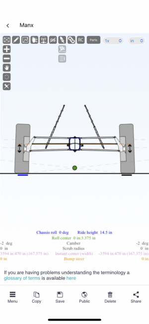
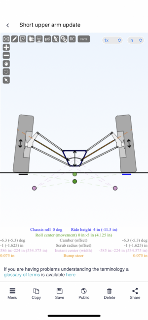
1st concept:
24.125” lower control arm
21.75” upper control arm
6” separation between upper arm pivots at bulkhead
6” separation between lower arm pivots at bulkhead
7” vertical separation between upper and lower arms at bulkhead
8.5” between pivots at spindle.
0 scrub
-2* camber at ride height
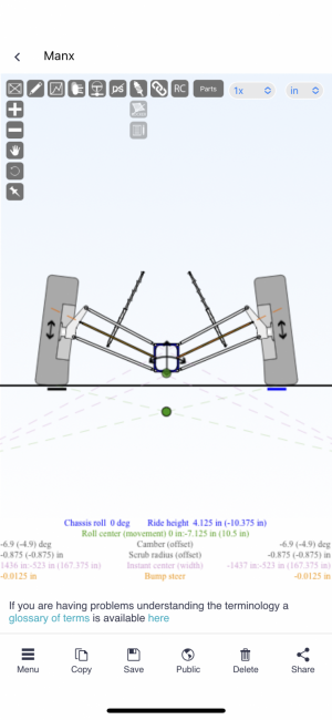
-7* camber at bump
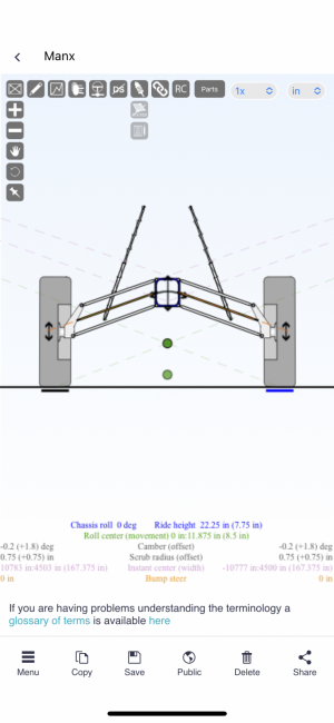
0* camber at droop
~3” lateral scrub (track width change) over 18” of travel.
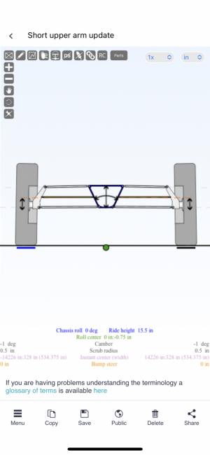
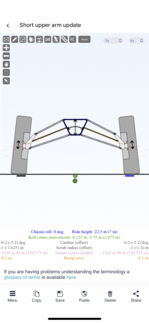
2nd concept:
24.25” lower control arm
17.75” upper control arm
13.5” separation between upper arm pivots at bulkhead
5.5” separation between lower arm pivots at bulkhead
8.375” vertical separation between upper and lower arms at bulkhead
8.5” between pivots at spindle
.5” scrub radius
-1* camber at ride height
-6.3* camber at bump
-6.2* camber at droop
Less than 1” lateral scrub (track width change) over 18” of travel.
11.5” of up travel, 7” droop travel.
//
I figure the 2nd concept will be better based on the lack of lateral scrub.
This is my first time designing an arms and I’d appreciate input on the parallel design vs the short upper design. Also would love some feedback on where I can make improvements.
1st concept:
24.125” lower control arm
21.75” upper control arm
6” separation between upper arm pivots at bulkhead
6” separation between lower arm pivots at bulkhead
7” vertical separation between upper and lower arms at bulkhead
8.5” between pivots at spindle.
0 scrub
-2* camber at ride height
-7* camber at bump
0* camber at droop
~3” lateral scrub (track width change) over 18” of travel.
2nd concept:
24.25” lower control arm
17.75” upper control arm
13.5” separation between upper arm pivots at bulkhead
5.5” separation between lower arm pivots at bulkhead
8.375” vertical separation between upper and lower arms at bulkhead
8.5” between pivots at spindle
.5” scrub radius
-1* camber at ride height
-6.3* camber at bump
-6.2* camber at droop
Less than 1” lateral scrub (track width change) over 18” of travel.
11.5” of up travel, 7” droop travel.
//
I figure the 2nd concept will be better based on the lack of lateral scrub.
This is my first time designing an arms and I’d appreciate input on the parallel design vs the short upper design. Also would love some feedback on where I can make improvements.
Attachments
Last edited: