Reducing the reliability of a first gen Tundra (01 2wd->4wd S/C Build)

Any updates? Planning on dyno'ing this thing?

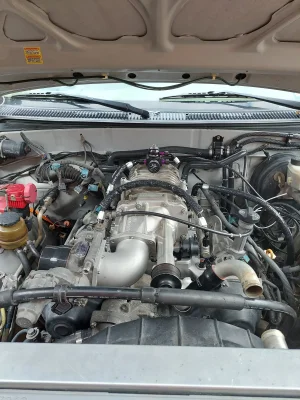
I have an access cab tundra with a TRD Blower on it that the cats and head unit were stolen from when it was stored in LA. Ins decided to total it out, so I bought it back, plan to pick up a 4 door tundra, probably 05/06 as a fam hauler that I will swap everything over too. Moved to AZ too, so I picked up some long tubes, curious on power numbers the setup will put down.

It will likely get dynoed but not for a while.

If you find longtubes anywhere let me know. The JBA ones are unavailable last I looked.

As for updates, I am neck deep in wiring, right now. I have most of the main harness laid out and ready to test but we had the hurricane come though and interrupt my progress, then it rained all last week.

I am currently working on getting the stock 2011 Range Rover throttle body that bolts to the tvs supercharger, and the later model 05/06 tundra dbw accelerator pedal to talk to the stock 01 Tundra ecu. I have an adafruit feather rp2040 that I am setting up to read the new parts tps and aps signals and then output the "correct" range of signals for the 01 tundra. I have one more part on the way that will get here on Tuesday so I can test it but it is working on the bench so far.

I will try and get some pictures up later this week.

I also started working on the exhaust but have not made much progress. It is 2.25" from the headers into 2.25" magnaflow high flow cats, into a dual 2.25" inlet, single 3" outlet spintech muffler. I have it all tucked up really tight to the frame/body and am going to dump it on the passengers side over the frame either out the fender in a bezel or have it just barely poke out from under the fender.

Sean
 
I have been playing electrician, I have my aps/tps conversion stuff ready to try on the truck.

20240801_215748.JPG
The setup is an adafruit feather rp2040 microcontroller plugged into an i2c isolator to let the 0-5v signals from the tps/apps play nice with the 3.3v controller. An ads1015 adc reads the stock signals and the controller adjusts them before telling the mcp4278 dac what to send the stock ecu. It basically reads the new accelerator pedal position sensor (from a 2005 tundra) and the new tps (2010 range rover throttle body) and outputs a new signal that matches what the stock 01 tundra ecu expects to see. It works on the bench so I will see how it does on the truck soon.

I am hoping that the stock ecu control scheme will drive the new throttle motor, otherwise, I will run that through my megasquirt and just feed the stock ecu wiring another bullshit signal.

The rr throttle body is a little bigger bore than the stock one and it makes the install so much cleaner vs my janky elbow adapter and the stock throttle body. I also had an adapter/spacer cut so that I can add methanol ports/vac if I want to later.

Before
20231121_130005.jpg

After
20240610_180605.JPG

Sean
 
Well that didn't work when I tried it 2 weeks ago. The program did what it was supposed to (well, what I thought it was supposed to anyways) but it kept tripping the CEL when I moved the throttle blade which meant the throttle motor didn't move when I tried to use the accelerator pedal.

Nerd talk:

Since these are DBW pedals, they use 2 circuits for redundancy. One circuit is supposed to measure between 0.4-1.0V at closed and 3.2-4.8V at open. The other is supposed to measure between 2.0-2.9V at closed and 4.7-5.1V at open. Seems reasonable right? the RRSC throttle measured 0.885 closed and 4.545 open and 1.736 closed and 4.602 open. My little controller converted those raw voltage values into a percent, then converts those percentages into an equivalent voltage on the new range.

Code is here:

Python:
import board
import busio
import adafruit_mcp4728
import adafruit_ads1x15.ads1015 as ADS
from adafruit_ads1x15.analog_in import AnalogIn

i2c = busio.I2C(board.SCL, board.SDA)
ads = ADS.ADS1015(i2c)

mcp4728 = adafruit_mcp4728.MCP4728(i2c, 0x60)
ads.gain = 2/3
aps1in = AnalogIn(ads, ADS.P0)
aps2in = AnalogIn(ads, ADS.P1)
tps1in = AnalogIn(ads, ADS.P2)
tps2in = AnalogIn(ads, ADS.P3)

aps1inmin = 0.78
aps1inmax = 4.35
aps2inmin = 1.59
aps2inmax = 4.99

aps1outmin = 0.6
aps1outmax = 4.0
aps2outmin = 2.25
aps2outmax = 4.9

tps1inmin = 0.870
tps1inmax = 4.54
tps2inmin = 1.69
tps2inmax = 4.46

tps1outmin = 0.829
tps1outmax = 4.278
tps2outmin = 2.6
tps2outmax = 5.07

while True:

    aps1pct = (aps1in.voltage - aps1inmin) / (aps1inmax - aps1inmin)
    aps2pct = (aps2in.voltage - aps2inmin) / (aps2inmax - aps2inmin)
    tps1pct = (tps1in.voltage - tps1inmin) / (tps1inmax - tps1inmin)
    tps2pct = (tps2in.voltage - tps2inmin) / (tps2inmax - tps2inmin)

    aps1outv = (aps1pct * (aps1outmax - aps1outmin)) + aps1outmin
    aps2outv = (aps2pct * (aps2outmax - aps2outmin)) + aps2outmin
    tps1outv = (tps1pct * (tps1outmax - tps1outmin)) + tps1outmin
    tps2outv = (tps2pct * (tps2outmax - tps2outmin)) + tps2outmin

    aps1outdac = aps1outv * 65535 / 5
    aps2outdac = aps2outv * 65535 / 5
    tps1outdac = tps1outv * 65535 / 5
    tps2outdac = tps2outv * 65535 / 5

    mcp4728.channel_a.value = int(aps1outdac)
    mcp4728.channel_a.vref = adafruit_mcp4728.Vref.VDD

    mcp4728.channel_b.value = int(aps2outdac)
    mcp4728.channel_b.vref = adafruit_mcp4728.Vref.VDD

    mcp4728.channel_c.value = int(tps1outdac)
    mcp4728.channel_c.vref = adafruit_mcp4728.Vref.VDD

    mcp4728.channel_d.value = int(tps2outdac)
    mcp4728.channel_d.vref = adafruit_mcp4728.Vref.VDD

I can measure the voltage outputs on the controller and it matches what I am asking it to but it was still triggering the CEL. It could be that the controller boots up too slow to trick the ecu or I may be missing something else.

I picked up an 05 Tundra throttle body to play with since the voltage outputs on the 01 and 05 Tundra TPS match. Hopefully this will let me see if my converter is the problem or if something else is to blame. If the 05 Throttle works, it means I can use the GS-F Throttle which should be close in size to the RRSC Throttle. It also means I derped something up so we will see.

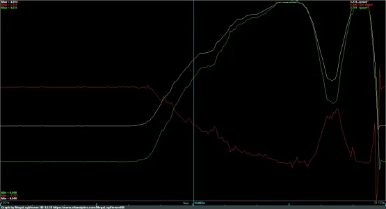
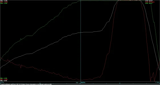
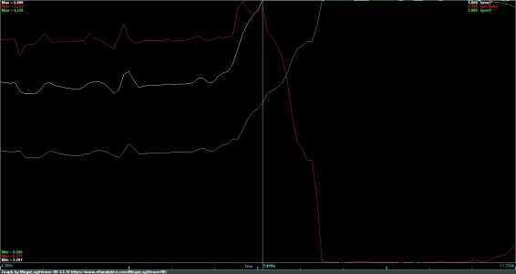
I also found out that the TPS2 range is not strictly linear. It is more or less linear until about 50-70ish% and then it hits its peak and holds there. TPS1 is essentially linear. I confirmed that on the 01, 05. (EDIT: I just double checked the RRTPS and that does not happen like I thought it did.)

1723601158366.png

The other thing that the ECU may be checking for is the resistance/current/voltage between pins 1 and 4 (VCC and Ground) on the TPS at key on or start but I can't really fake that.

Sean
 
Last edited:
The new 05 Tundra DBW throttle pedal also tripped the same codes for P0120 and P0121 despite having the same sensor voltage output range as the stock 01 throttle.

There has to be some kind of check that I am missing here. I am wondering if the voltage vs percentage on tps1 and tps2 is off relative to the stock 01 Tundra throttle, like the shape of the curve between 0 and 100% is different somehow. Not sure, for now, I am going to just run the 01 Tundra throttle. I may try hacking up one of these other throttles to see if I can mod the throttle to use the 01 Tundra TPS sensor externally and just run that way. I also have the option of adding the tundra throttle motor and tps from the 01 to the other throttle but that will take some work to do.

Sean
 
Looks like I may have derped, the weird step I found on tps 2 for the tundra is not on the RRSC tb like I thought. I added another value and an if/else statement on the code that creates that step. It works on the bench but I will have to test on the truck later this week since its 10pm here. I need to check and see if the APPs does the same thing or not. I also need to add a statement that says if the dac value out is > 65535, revert to the max so it doesn't crash.

Python:
# APPS and TPS Converter
import board
import busio
import adafruit_mcp4728
import adafruit_ads1x15.ads1015 as ADS
from adafruit_ads1x15.analog_in import AnalogIn

i2c = busio.I2C(board.SCL, board.SDA)
ads = ADS.ADS1015(i2c)

mcp4728 = adafruit_mcp4728.MCP4728(i2c, 0x60)
ads.gain = 2/3
aps1in = AnalogIn(ads, ADS.P0)
aps2in = AnalogIn(ads, ADS.P1)
tps1in = AnalogIn(ads, ADS.P2)
tps2in = AnalogIn(ads, ADS.P3)

aps1inmin = 0.78
aps1inmax = 4.35
aps2inmin = 1.59
aps2inmax = 4.99

aps1outmin = 0.6
aps1outmax = 4.0
aps2outmin = 2.25
aps2outmax = 4.9

tps1inmin = 0.91
tps1inmax = 4.54
tps2inmin = 1.75
tps2inbreak = 3.5
tps2inmax = 4.65

tps1outmin = 0.829
tps1outmax = 4.25
tps2outmin = 2.60
tps2outmax = 5

while True:

    aps1pct = (aps1in.voltage - aps1inmin) / (aps1inmax - aps1inmin)
    aps2pct = (aps2in.voltage - aps2inmin) / (aps2inmax - aps2inmin)
    tps1pct = (tps1in.voltage - tps1inmin) / (tps1inmax - tps1inmin)
    tps2pct = (tps2in.voltage - tps2inmin) / (tps2inbreak - tps2inmin)

    aps1outv = (aps1pct * (aps1outmax - aps1outmin)) + aps1outmin
    aps2outv = (aps2pct * (aps2outmax - aps2outmin)) + aps2outmin
    tps1outv = (tps1pct * (tps1outmax - tps1outmin)) + tps1outmin
    tps2outv = (tps2pct * (tps2outmax - tps2outmin)) + tps2outmin

    aps1outdac = aps1outv * 65535 / 5
    aps2outdac = aps2outv * 65535 / 5
    tps1outdac = tps1outv * 65535 / 5
    if tps2outv > tps2outmax:  
        tps2outdac = 65535
    else:
        tps2outdac = tps2outv * 65535 / 5

    mcp4728.channel_a.value = int(aps1outdac)
    mcp4728.channel_a.vref = adafruit_mcp4728.Vref.VDD

    mcp4728.channel_b.value = int(aps2outdac)
    mcp4728.channel_b.vref = adafruit_mcp4728.Vref.VDD

    mcp4728.channel_c.value = int(tps1outdac)
    mcp4728.channel_c.vref = adafruit_mcp4728.Vref.VDD

    mcp4728.channel_d.value = int(tps2outdac)
    mcp4728.channel_d.vref = adafruit_mcp4728.Vref.VDD
Sean
 
I have a little more tuning to do on the break point but the concept works. I am going to try and test on the truck this week.

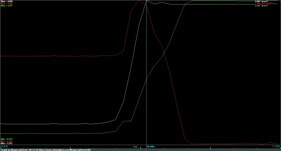
Essentially, tps2 peaks when tps 1 is only about 2.8v on the yota ones. I didn't have that value right because my code was just converting the signal into the right range without checking the shape.

01 Stock Tundra/DensoTPS
01 TPS Graph.png

05 Stock Tundra (ebay tb)
05 tundra tps.png

11 Stock RRSC/fomoco
11 RRSC Graph.png

Sean's secret sauce converter on 11RRSC TB after update.
corrected rrsc tps.png

Sean
 
I got the TPS converter working finally, I will upload the code once I have the accelerator circuit tested as well.

The nice thing too is that I was able to power the converter off the 5v rail on the TPS circuit so no need to add any other power converters or anything.

The new and exciting problem is this


I need to measure the control inputs on the tb motor dive circuit and figure out how to tune that for the new motor. I am guessing the tundra is using a 12v pwm signal and the rrsc one is using 5v but I will confirm that with a scope.

That is a tomorrow problem though since it is 11:23 already.

Sean
 
Last edited:
Sun up update, I went out to measure with my chinesium o-scope and it does look like I am getting a 12v PWM signal to the tb. I can't confirm it because the pause function on my scope is not working (or I am not using it right) but if I manually pulse 12v to the throttle motor it does essentially the same thing. Both motors will fully open at ~2.5V 1ish amp constant duty DC so I grabbed a PWMable Mosfet that I am hoping to be able to use the stock TB motor pulsed 12v signal to trigger, then have that mosfet feed a 5v pulsed signal to the TB. This way, it will just function like a level shifter. If the throttle body responds too slow, I can up the voltage, if it is too fast or twitchy, I can give it a lower voltage and the factory ecu should still think nothing has changed. If that doesn't work, I am just going to read the pulsed signal into the same controller I am using for the TPS and use a stepper driver to directly drive the tb.

Quality electronics I picked up to test (Amazon product)

Sean
 
Testing update, and it's not great.

I ran with the level shifter last night and it is still kind of jerky. I may be able to smooth that out with an R-C circuit of some kind but I ran out of time today to get too far in it. Evidence below.


I also tested today with a 13.7 ohm resistor in line with the rrsc throttle motor, the throttle body doesn't move. With a 10 ohm resistor it barely moves, with a 5 ohm resistor it wiggles. I am thinking a 7 ohm will get me in the ballpark with the stock circuit but I don't have any on hand. Yes, I could have done 2 resistors in parallel but I didn't do that for some reason.

So I took the stock throttle body and played around with it again. The video below is no clutch, then with the clutch on, then clutch off again. I think that because of how the clutch and gear reduction works on that motor the pwm signal just holds it in place since the throttle blade is basically in peanut butter.


I need to get my scope working properly and see what the signal really looks like and probably pickup some bigass caps to play with.

If any of y'all have any suggestions on other things to tame the wiggling without freaking out the stock ecu, I am open to suggestions.

Edit: I wonder if I can just do a voltage divider on the input side to the motor to dump the voltage from 12v to something lower and that may smooth that jitter out.

Sean
 
Last edited:
Can't argue that point.
I would like to help but I have no idea what you’re doing.
Man, I have that same problem just in general.

I need to get the stock ecu on my 2001 tundra to drive the 2011 range rover throttle body I have on the supercharger I am installing. I have the tps signals converted with an adc - dac converter and controller so the tps is in range but the pwm signal that the stock tundra ecu uses to move the throttle motor itself is making the butterfly jump around. Its behaving like the base voltage is too high or the frequency of the pwm signal is too low which makes the butterfly bounce when used with the range rover throttle

I have tried so far, running a resistor inline on the pwm feed to the throttle motor in a few different resistances, running an intercept circuit to use the stock throttle drive circuit to trigger a mosfet to power the throttle with 5v instead of 12v but it is still jumpy. I was hoping that by changing the voltage or adding the resistor, it would make the blade less jumpy on the open command and that the throttle spring was roughly the same as stock so it would float closed at the same rate. But testint didn't support that.

In my last post, I was showing how the stock throttle clutch/gear reduction kind of acts like a dashpot to slow the blade down which may be smoothing the bounce out on the stock throttle. Which is also why playing with the voltage didn't help.

I think I am going to have to resort to reading the tps signal into the microcontroller I am using, then interpreting what the ecu wants (more throttle, less throttle, no change) and driving the motor with a new pwm signal but I was hoping to avoid that.

Sean
 
Last edited:
Here is how the stock throttle looks on the stock ecu with no intervention. I basically need the range rover throttle do do the same thing, for a given apps input, I need the same tps output. Since it is not a 1:1 ratio, thanks ects-i, I was thinking I could just intercept the pwm signal and use how that changes over time to approximate more open vs less open vs hold steady.


The stock 01 throttle makes a high frequency hum when the motor is on but I am not sure if you can hear it in the video since my neighbors yard crew was out there.

Sean
 
Last edited:
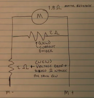
Thinking about it again. I am wondering if the ecu is firing pulses on both wires to the throttle motor. When I was playing with the throttle body this morning, I couldn't manually open it when the motor was powered. Which means the motor is energized in the closed direction since it is just a brushed dc motor. It could also explain the high frequency noise. It looks like it is probably an H bridge circuit based on that.

I had assumed that the motor drive circuit acted in the open direction only which would partially explain why my step down circuit didn't work. It was triggering 5v on one leg only and it cut out the reverse side entirely.

Edit: I need to test this but it should clip the motor voltage a little bit and cut current to the motor by a pretty good chunk.

I am going to add a 2 ohm resistor inline to the motor on one leg, then add another one in parallel with the motor to act as a current divider. The inline one will keep the circuit current low enough not to freak out the ecu or fry anything and the dividing resistor will pull a chunk of current away from the motor itself to take some of the torque away since the load on the shaft is a lot less. It should also slow the motor down a bit since the voltage will drop from the inline resistor. I just need to make sure I don't overdo it.
1000022713.jpg

Sean
 
Last edited:
I snagged another stock throttle to cut up and am going to try and see if I can adapt the stock Tundra throttle motor and TPS to the RRSC throttle body. It just showed up yesterday so I need to take it apart to measure eveything now.

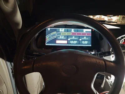
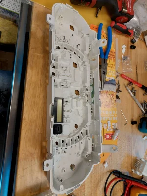
In the meantime, I got most of the wiring ready to test and last night got the dash and rpi powered on the truck. It was a good milestone since wiring this up has been a big job. The dash layout is just the default one for now. Ill post in more detail about how this is actually setup once I get time.

I am making it a goal to knock one item off my to-do list every other day, the smaller stuff can be done midweek I think. Its a pretty gnarly list but I think I can make things move along more.

Sean

20240908_203923.JPG
 
Last edited:
What hp/tq are you looking to be at after all of this?
Less than a stock LS or 5.7 yota lol.

Probably 330ish. Its in the neighborhood of 245 now from some dyno charts. Have seen floating around.

If I do rods I could be north of 400 without much more than a pulley change and tune though. That may end up happening at some point.

Really, I want reliable and cool temps and other than that, its just for the boost noises and whatever I get.

Sean
 
Last edited:
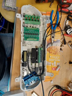
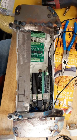
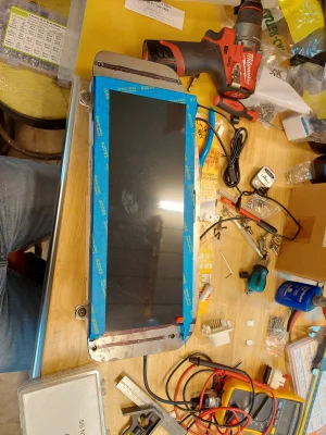
Here is the background on the gauge.

8gb rpi 4b+
Waveshare 12.3" display
11 channels of optoisolated level shift to pull factory io from the dash, I may swap to 2, 8 channel modules in the future so I can do more transmission control/disply atuff.

Running ts dash it will pull info straight from the ms3 and let me tune if I want. It will also run DOOM since it is just a raspberry pi. Ill end up switching to a pi5 when it becomes available in tsdash.

Sean

20240218_122439.jpg

20240218_122436.jpg

20240218_122407.jpg

20240218_122630_1.jpg

20240218_122654.jpg

20240218_122703_1.jpg
 
Last edited:
Back
Top