1968 Ford F-250 Prerunner Build Thread

85Yota

Well-known member
Joined
Apr 5, 2022
Messages
967
Copy and paste from other sites but same info.

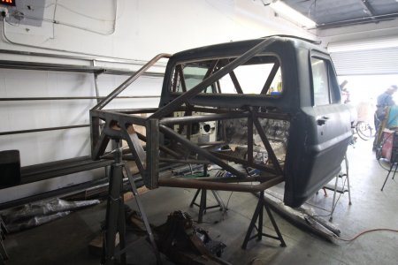
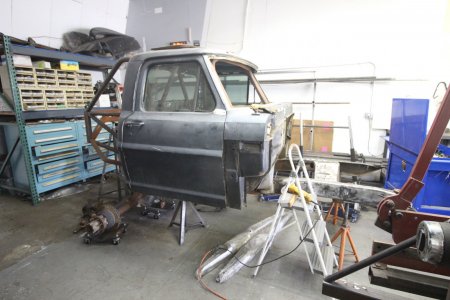
Ok so I have a 1968 Ford F250 that was previously a prerunner and I am rebuilding it into a 4x4 badass prerunner.

Going with a 6.0L LQ4 with forged bottom end since I'm running a single turbo on. 4L80e Trans and Ford NP205 T-case.

Equal length D50 TTB front end. Fox 3.0 coilovers and 3.5 bypasses and 2.0 air bump

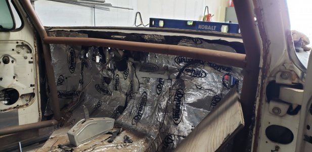
Cab will be getting 3 seats across with middle PRP seat being slightly smaller and easily removable to make room for a nice cooler/Fridge to do in its place when going on a weekend trip with only 1 person, 3 seats will be for weekends in glamis and such to give more rides.

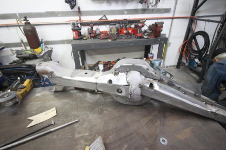
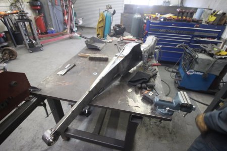
Rear is D70 Dually axle that is trussed and tabbed. D80 Spool with 37 spline chromo axle shafts. 5.13 gears since lowest gears I can run in the front end. 3.0 coilover and 4.4 Fox Bypass out back 2.5 air bump.
Most Likely going to run a different rear axle since the track width difference is quite a bit.

Trail Ready Beadlocks with BFG 40" tires

Single spare tire

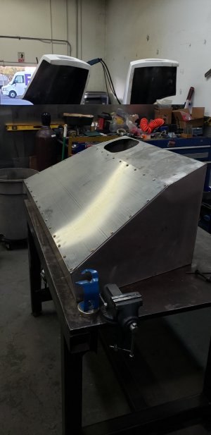
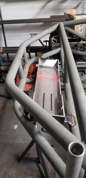
Rear will also be running a Harmon Fuel Cell bladder in a custom can that I made. Approx 55 gallons

Cab will be getting all windows put back in along with a aftermarket Restomod AC system, heater and Stereo along with my Tablet mounted for GPS and Torque app when needed.

Mcqueen Front Fiberglass and Mcneil rear bedsides like the brodozer since i want to run stock tail lights as well.


Follow along with my instagram.com/tt.motorsports and my youtube since I'll be posting updated videos and photos on there as well as here.

How it started. I got this truck in a trade as a "complete" prerunner that I parted out so essentially started with the registered pre smog truck for free. Started collecting parts and some of the fab work back in 2014. Worked on it for a couple years between jobs, stole some parts like trailing arms for my tacoma. Upgraded the coilovers from 2.5s to 3.0's but here's where the work started on it again after having it as a roller at my last shop in Santa Maria.
IMG_4184.JPGIMG_4183.JPGIMG_4182.JPGIMG_4181.JPG20210307_125102.jpg20210307_125059.jpg20210307_125055.jpg20210307_125043.jpg20210307_125037.jpg
 
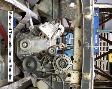
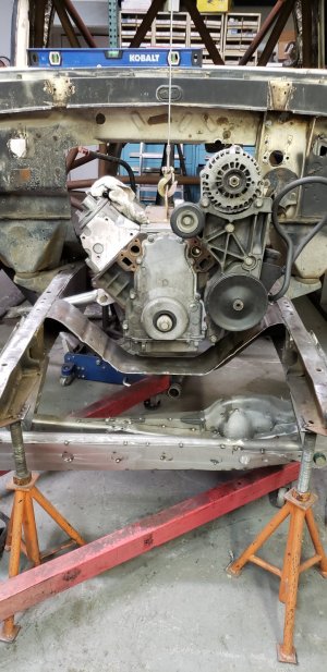
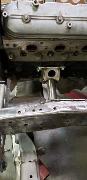
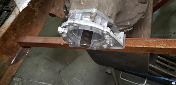
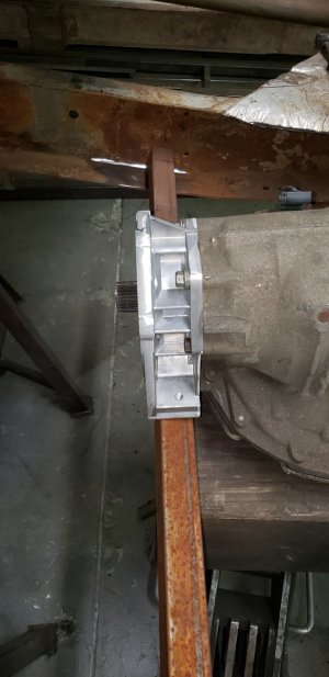
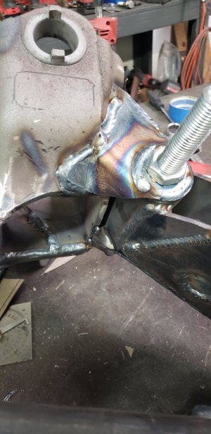
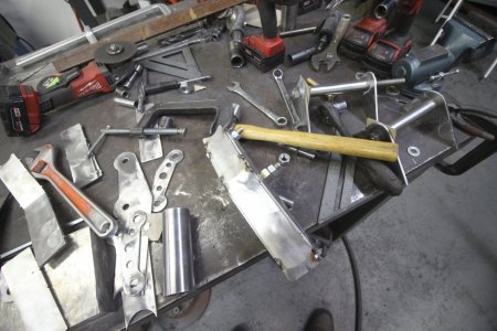
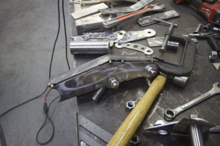
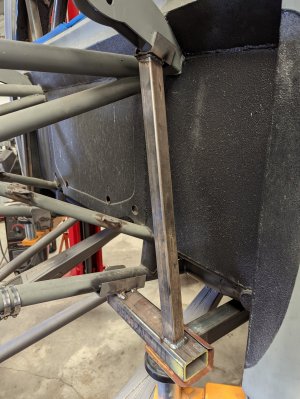
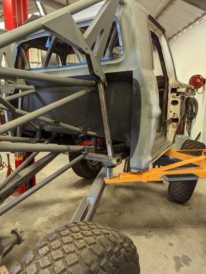
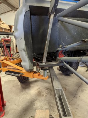
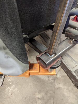
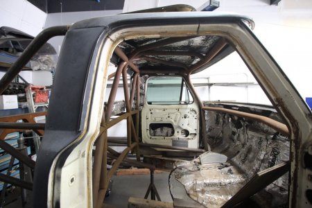
I'm jumping around but next was mounting the motor/trans. cutting out the entire firewall, floor and rear firewall, along with boxing the frame and removing the rear steer box and am converting to front steer with a sagniaw box from a 3/4 Ton truck. Another big piece of the puzzle was mating the Ford NP205 t-case behind the GM 4L80E transmission. I changed the Ford Input shaft to a GM input shaft. I then got a ford NP205 Clocking ring. with using a variety of bolt options since it had 2 amounts of clocking I was able to get it to line up with the factory 4L80E t-case adapter housing from a GM truck. This Transmission was also a 2WD transmission so after sliding it all together I measured the gap between the clocking ring and the t-case adapter which was 2 3/8" so I slid t-case off and cut the 2wd output shaft 2 1/2" and it all mated together perfectly and the t-case is flat and completely above the bottom of the frame. Only issue I had with this is that the t-case is really close to the driver side link mount so I was able to cut/hammer/reweld that to get it to all clear. Looking back I should have mounted the drivetrain offset to the passenger side 1/2" would have made my life a bit easier.
Step 6 Thumbnail.jpg20210312_180748.jpg20210312_180753.jpg20210313_142853.jpg20210313_171536.jpg20210313_171542.jpg20210313_171641.jpg20210313_171648.jpg20210313_172132.jpg20210313_172137.jpg20210313_172141.jpg20210409_130400.jpg
 
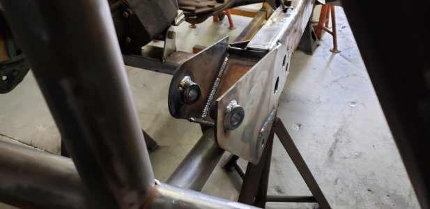
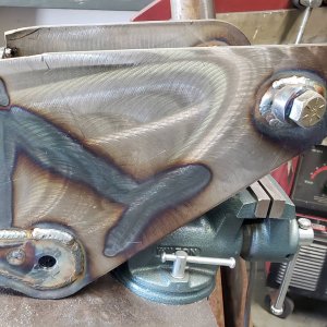
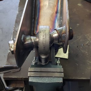
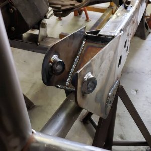
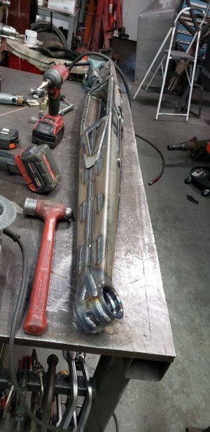
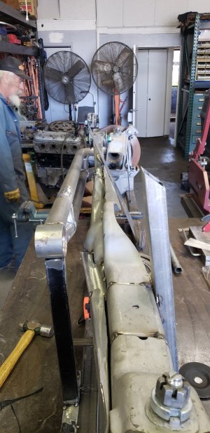
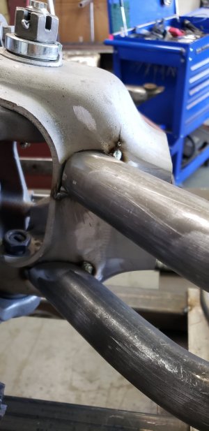
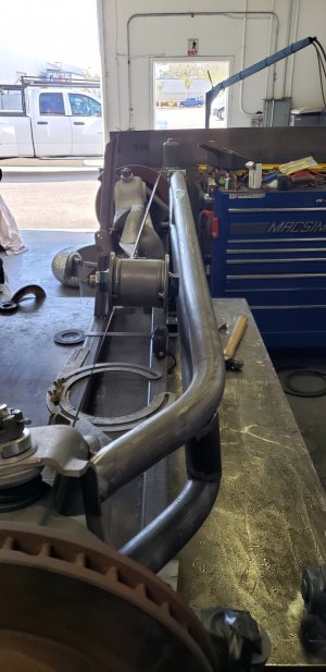
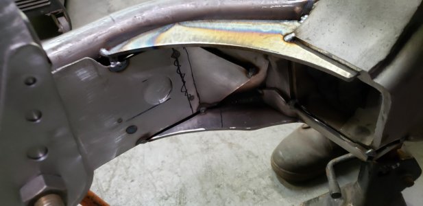
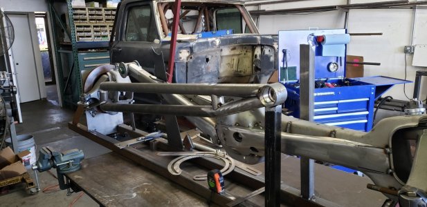
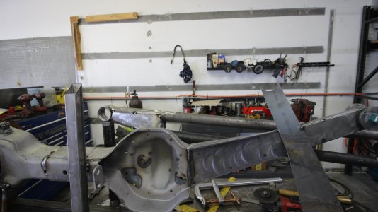
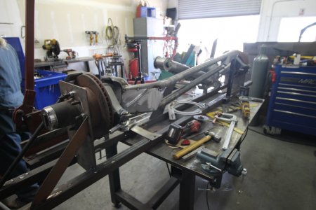
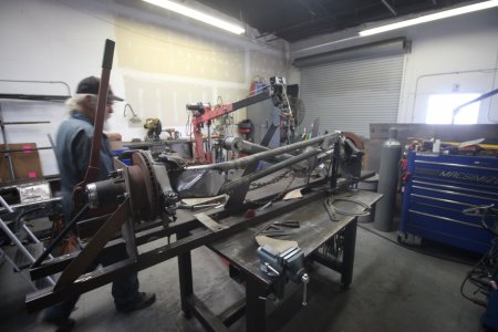
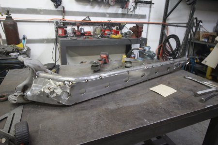
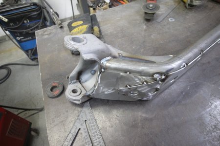
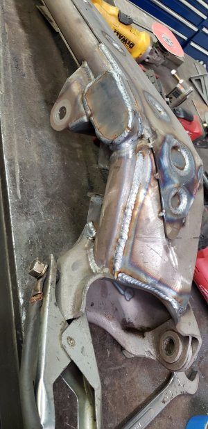
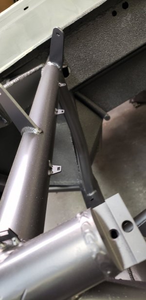
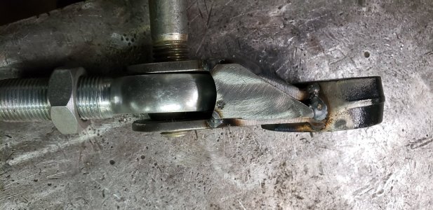
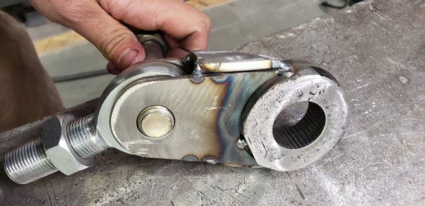
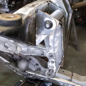
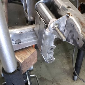
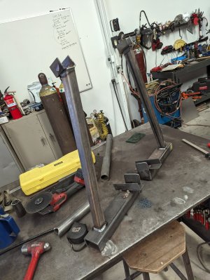
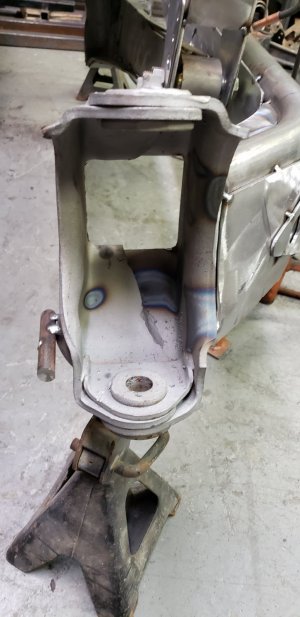
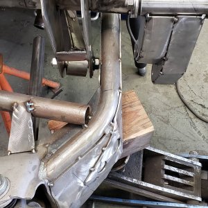
Ok so as you can see I got the beams mounted up onto the truck. This is where it gets weird and I hope that all the cycling and everything done in the shop works in the field. I had a set of D50 TTB from a 1996 Ford F-250. I originally got these as part of a package deal because I wanted the spindles and hubs to build 2wd beams for this truck. Well my last tacoma the only thing I wish that truck had was 4x4 since it couldn't make it some places even with the 37s spool and aired down tires. So I wanted to do a TTB Swap on this. Now D50 beams are shorter than D44 and with some quick cycling on the shop floor it was only going to swing around 18" of travel. For this truck I was wanting more. I remember seeing Ramset on RDC building Raquel a Equal length TTB Blazer. I studied the photos and figured I would make it happen. So I started constructing a fixture to build the beams off of on the bench. Figured out the WMS width I wanted to have the tires fit the mcqueen glass I got. Then cut the beams and started fitting them up on the bench. Tons of measurements to figure out beam pivot widths and height and got the uniball cups tacked itno place where I wanted them. Then started connecting the dots. As you can see the passenger side beam had to have a bend to go infront of the pumkin to get longer beams. The one thing that I will change in future is I will make some custom knuckles so I can weld the Tie rod in a different location to get straighter or possibly straight tie rods. I am currently running drilled and tapper 1 1/4" x .375 4130 tubing and 7/8" heims. To keep the bent tie rods from flopping I welded some pinch bolt tabs and slid the inner thread. To keep them from bending more I had them heat treated. Hopefully I don't have a problem BUT if I do I have a solution, aka rebuild my entire steering/swingers/pitman arm etc.
20210305_150902.jpg20210307_124953.jpg20210308_113455.jpg20210308_145735.jpg20210308_145740.jpg20210308_145746.jpg20210308_145751.jpg20210311_143141.jpg20210311_143149.jpg20210312_180857.jpg20210312_180905.jpg20210312_180907.jpgBeams 1 thumbnail.jpgIMG_4174 - Copy.JPGIMG_4175 - Copy.JPGIMG_4186 - Copy.JPGIMG_4213 - Copy.JPG
 
Last edited:
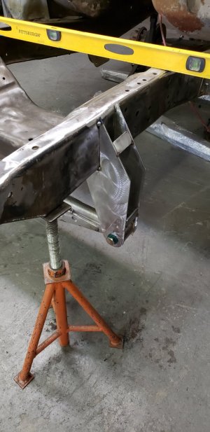
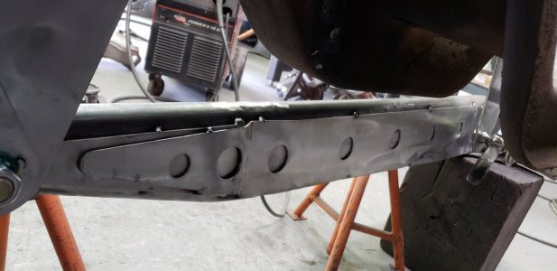
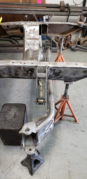
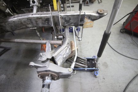
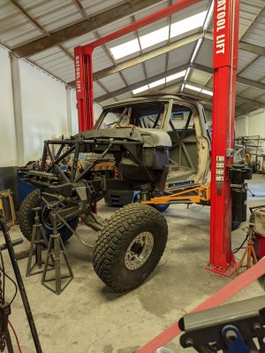
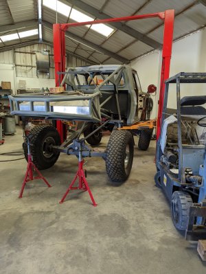
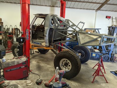
Now the the beams were all tacked together I didn't have them boxed in yet I started mounting them on the truck and cycling them. So I gotta set the wheelbase even from side to side and build radius arms. I set the frame and wheel hub both at ride height. Then I set the caster at 10 degrees and tacked on some tubes imitate radius arms. Got beam pivots on the truck and the pass inner axle needed to slip around 4" to achieve full travel, with driver bump pass droop to both droop that plunge. Factory axle only has around 2" of slip BUT the D50 axle runs a 1350 u-joint so I was able to get a 7" slip made for driveshafts that I'm gonna use and hope the 1.5" x 16 spline doesn't have a problem, if so I will be on the search for a 1350 slip yoke with 31ish splines and have custom shafts made for that. Well the axle would contact the driver beam pivot bolt. So I cut some tacks and put a slight kick in that beams and moved driver beam pivot forward a bit when doing that so everything cleared. Then I removed them after everything cleared and started to box them in because attaching radius arms is next.

20210311_143141.jpg20210311_143149.jpg20210311_172410.jpg20210311_172413.jpg20210312_113558.jpg20210312_113603.jpg20210312_180853.jpgIMG_4225 - Copy.JPGIMG_4225.JPGIMG_4228 - Copy.JPGIMG_4228.JPGIMG_4229 - Copy.JPGIMG_4231.JPGIMG_4232.JPGIMG_4233.JPG
 
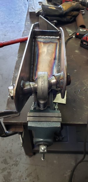
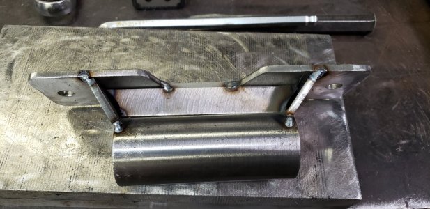
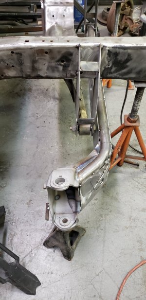
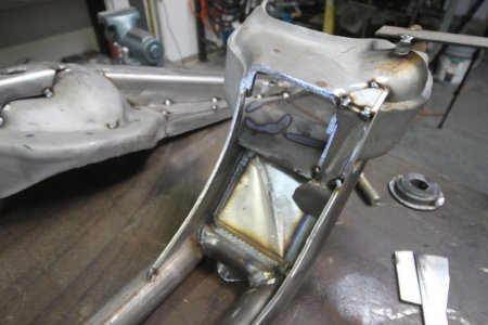
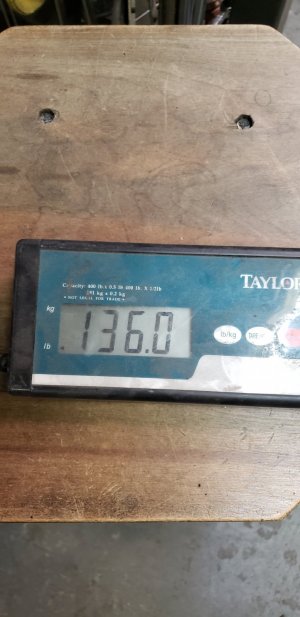
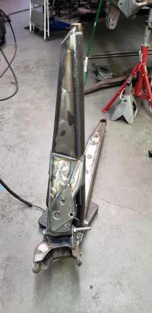
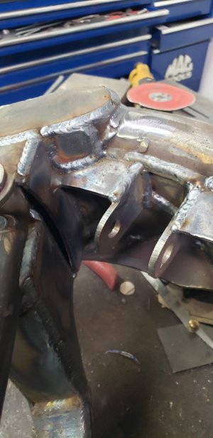
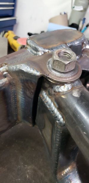
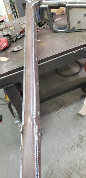
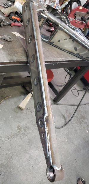
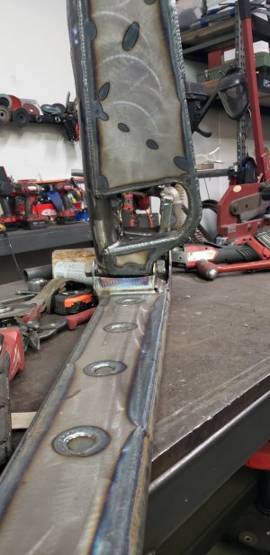
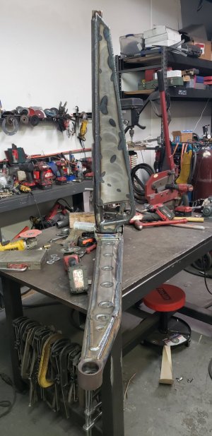
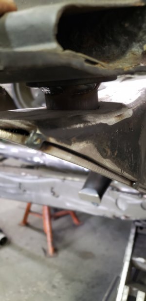
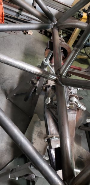
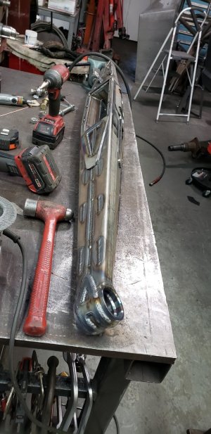
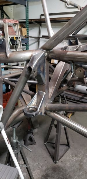
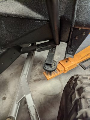
Now the passenger side radius arm needed a hole for that axle to pass through where the pass beam had a hole before. I had 16" co and 18" bypasses and I saw they would fit so I ran them. The coilover had to mount behind the beam and the bypass off the front, on driver side. Well Passenger side beam being so strange the bypass is close to back of the beam and coilover on the radius arm. Do mount that coilover and made it strong enough, I machined some 1.75" x .5" wall tubing and then welded that inside some 2" tubing, tig around the end with a nice bevel on the piece so even after machining it had a full weld. Only found pictures of them done BUT the first is the scale which shows the weight on 1 beams/radius arm together.

20211124_105628.jpg20211124_105625.jpg20211123_161954.jpg20211123_161950.jpg20211123_161947.jpg20211123_161938.jpg20211123_161934.jpg20211123_161902.jpg20211123_161859.jpg20211123_161759.jpg20211123_161754.jpg20211123_161750.jpg20211121_154502.jpg20211121_154330.jpg20211121_154323.jpg
 
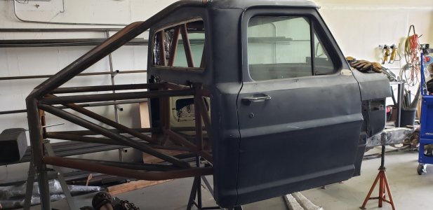
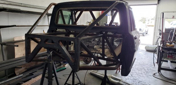
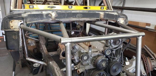
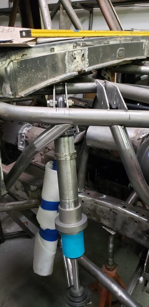
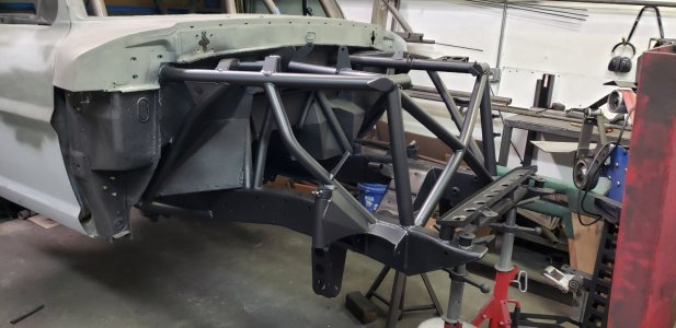
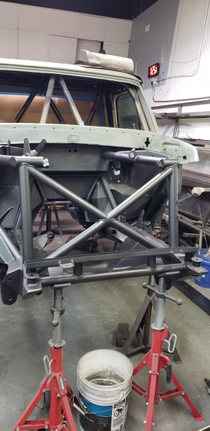
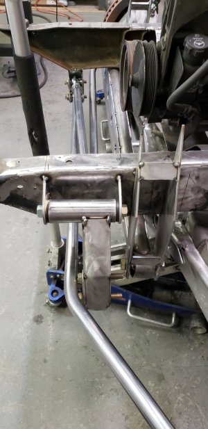
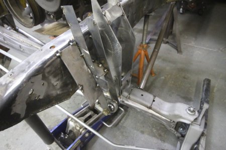
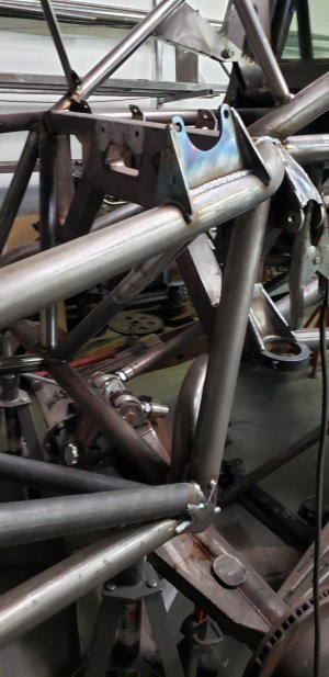
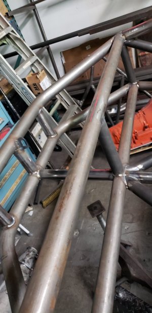
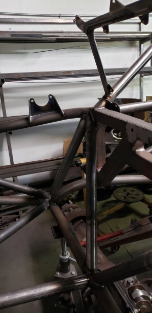
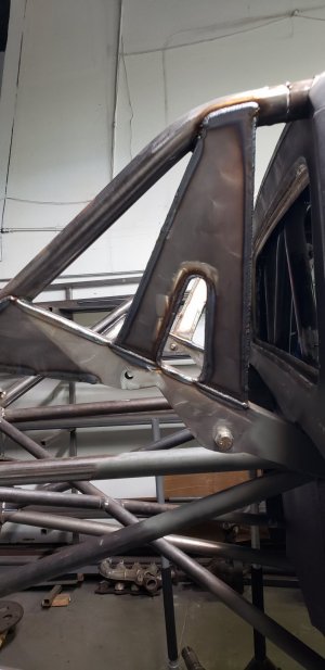
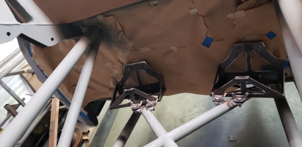
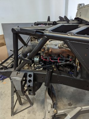
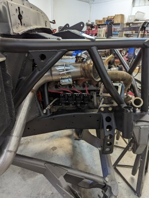
So beams and radius arms were tacked together before welded like above it was time for the engine cage/shock mounts and all that jaz. Patched some random vent holes in the cab as well.

20210423_140430.jpg20210424_162419.jpg20210424_162504.jpg20210424_162508.jpg20210523_164537 5.23.8.jpg20210526_194318.jpg20220202_132629.jpg20220202_132646.jpg20220202_132653.jpg
 
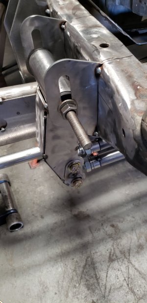
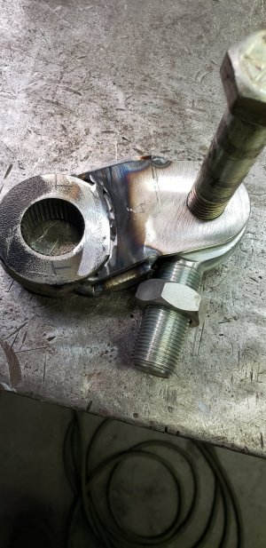
Now I just realized I jumped ahead and forgot before doing engine cage I had the steering mocked up. I learned that even 1/8" of change on inner tie rod pivot on swinger can affect the bumpsteer sometimes an inch. So I cut slotted tabs with washers to easily adjust them 1/16" at a time. Then when dialed in I tacked washer in place after putting digital level onto an 0 it out. Then I would remove 1 tab and make the final tab. Tack into place with bolt tigher and swinger 0 again. Then do the same for the other tab. Did that for both swingers to get the final position. Now once that was in position I measured how much horizontal movement the swinger connecting rod had. It is 4.25". So I measured steering box from full lock to lock with the 6" pitman arm I had then did some match and figured out the length of pitman arm I needed to get steering and box to cycle from full lock to lock. I did this becuase I have heard if you just use the middle of the steering box throw it wil wear it out quicker than using the entire steering box throw. I got it dialed after multiple days or checking and cycling with my dad helping, which he has been my shop helper for this entire build besides some of the first cab/backhalf stuff that Mikey helped me with when I lived in Simi Valley.


20210402_144733.jpg20210402_144738.jpg20210402_172052.jpg20210402_172101.jpg20210425_150815.jpg20210425_150822.jpg20210425_150826.jpgIMG_4413.JPGIMG_4414.JPGIMG_4415.JPGIMG_4416.JPGIMG_20210329_133314_298.jpgIMG_20210329_133314_325.jpgIMG_20210329_133314_339.jpg
 
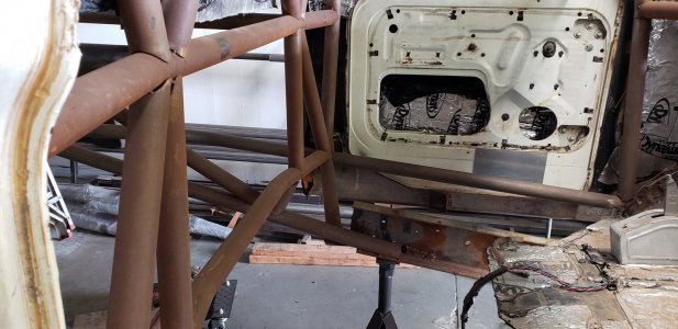
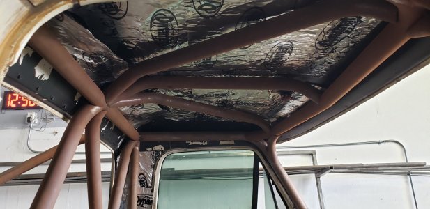
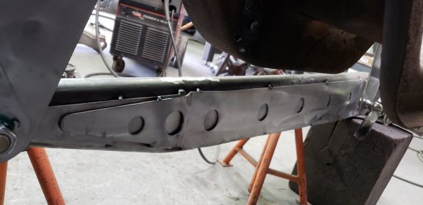
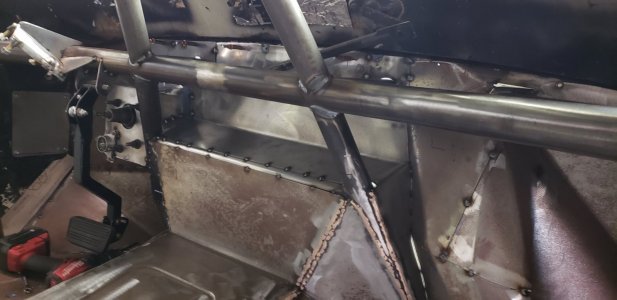
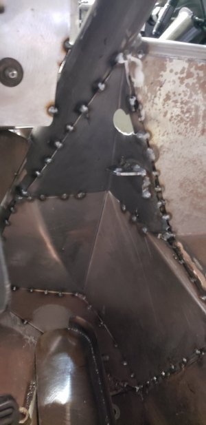
OK so I had the engine cage tacked up good BUT no firewall/floor boards. Time to get that back in place so I can fit the GM Hydroboost for brakes as well as the Ididit steering column and seats. No real good photos of this since I just wanted to get it done and would take photos at end of the say. Used some smaller tubing and some 18ga sheet metal and started fitting it all in place. Had to modify a few things for gas pedal and stuff BUT when building it I tried to keep as much interior room as I could while keeping the panels somewhat easy to build.

20210928_175637.jpg20210914_165620.jpg20210913_170110.jpg20210307_125020.jpg20210422_154022.jpg20210704_162605.jpg20210704_162632.jpg20210704_162642.jpg20210704_162645.jpg20210704_163314.jpg
 
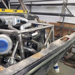
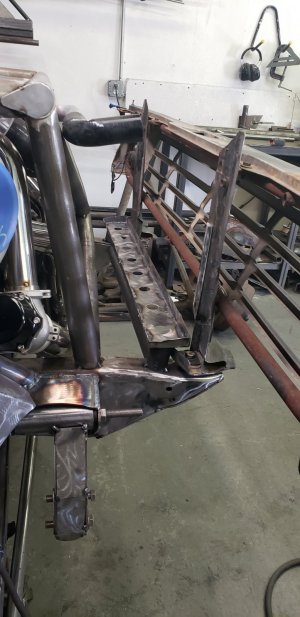
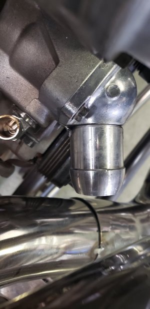
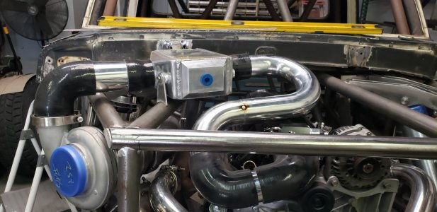
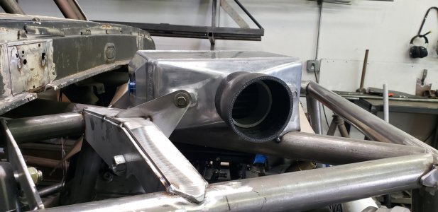
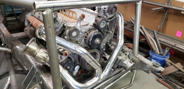
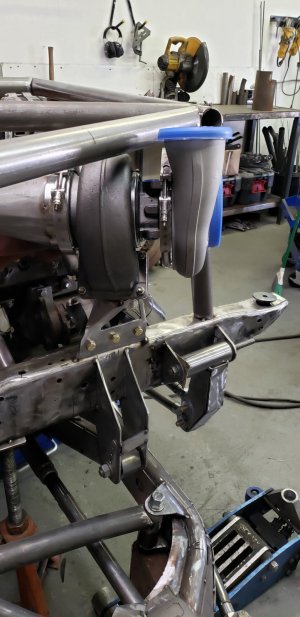
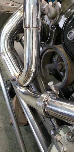
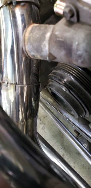
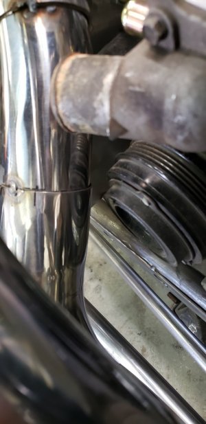
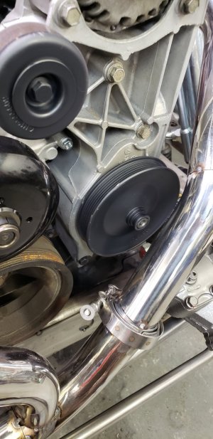
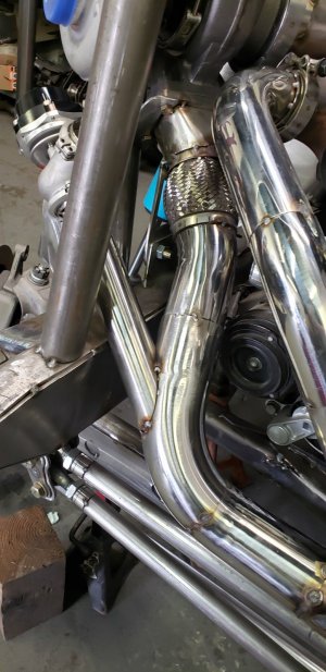
Ok so got the front pretty dialed in just need to finish weld it, gusset, mount radiator, ac condenser and air-water intercooler. Along with finihsing up the hot side plumbing of turbo, downpipe, waste gate etc. Made my own 3" to T6 flange sheet metal piece. I also hard mounted the turbo and full exhaust. The motor is on urethane bushings so before the turbo and wastegate I added some stainless flex couplers to hopefully keep it all good. 4" exhaust is big stuff to fit but since the turbo is outside pass frame behind headlight I was able to run the exhaust down and out back outside the pass side frame under the floor.

20210529_135210.jpg20210529_160748.jpg20210529_160756.jpg20210530_182124.jpg20210307_125020.jpg20210424_162657.jpg20210501_151931.jpg20210501_172124.jpg20210501_172129.jpg20210514_153449 - 1.jpg20210514_153449.jpg20210514_153453 - 1.jpg20210514_153453.jpg20210514_153503 - 1.jpg20210514_153503.jpg20210514_173106 - 1.jpg20210514_173106.jpg20210530_111248 wastegate 1.jpg20210530_111248 wastegate 2.jpgWastegate 1.jpg
 
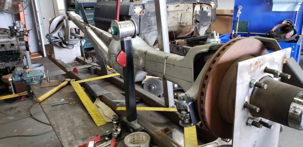
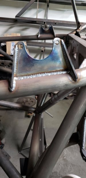
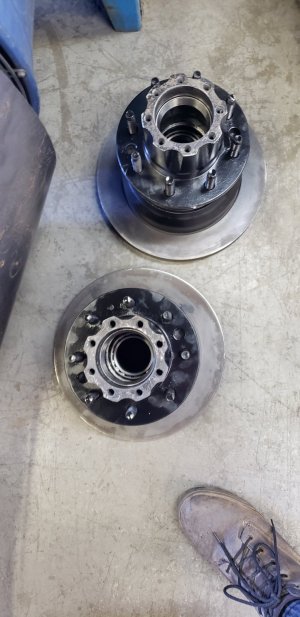
Now I was able to jump out back and get some of that stuff knocked out. First was get the axle cycling and at full bump so I could do shock mounts, rear fuel cell jack mount, spare etc. Got the rear hubs all cleaned up and new bearings, races and seals installed. Photo dump going on here. Ask any questions you guys have.

20211202_161102.jpg20211202_161108.jpg20211202_161114.jpg20211202_161117.jpg20211202_161121.jpg20211202_161137.jpg20211210_135759.jpg20211210_161647.jpg20211210_161654.jpg20211210_161659.jpg20211210_161707.jpg20211210_161716.jpg20220106_140806.jpg20220106_140814.jpg20220106_140906.jpg20220106_140909.jpg
 
this thing is going to be so fucking sick Tommy.

so fucking sick. it already IS. but when its done.............. holy fuck
 
Very nice! Looks like you might be able to use your OEM hood hinges still! Is that the plan or going a different route?
 
The truck didn't have OEM hood hinges, but I made hood hinges that are going to bolt to the cowl so the hood will lift like a factory hood once you undo the front hood pins. Also this year of trucks inner fenders is where the hood hinges mounted I believe
 
Back
Top