All HREW and flux core, yet less ghetto than before

TheMoneyPit

Member
Joined
Apr 4, 2022
Messages
60
Location
Missouri
(Copied from OG thread)

This Ranger started with a ghetto DIY mid travel kit, Camburg uprights, re-arched custom 64" junkyard leaf spring pack, King smoothies, and a donor 5.0+4r70w from an Explorer. Lots of labor and minimal money invested, yet a ton of fun. An excellent learning experience, but the bump steer with the DIY kit was fucking terrible (I was unwilling to modify the Camburg 5.5 kit spindles), and the Chevy-based leaf pack was always going to be stiff as hell.
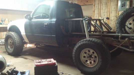
20190609_015350-min.jpg

Hoarded parts over the past six months or so before tearing the truck apart completely. Picked up a BTF race long travel kit, King 2.5 10" coilovers, Fox 2.0 bumps, basic 48" Ruffstuff four link kit, Giant 9 inch truss/axle side tabs, Threat chassis link pivots, factory Dana 44 hubs/spindles, RCI 32 gallon wedge fuel cell with a fuel level sender popped in, and a GM metric caliper conversion setup for the 9".
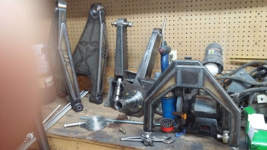
YGWITgn-min (1).jpeg

Most of the local steel places assume you're talking about pipe when you say "tubing", and even the better ones can't/won't order in DOM. Since options are limited, I picked up 220' of a mix of 1.75" .120 and .095 HREW tubing in the redneck tubing transporter.
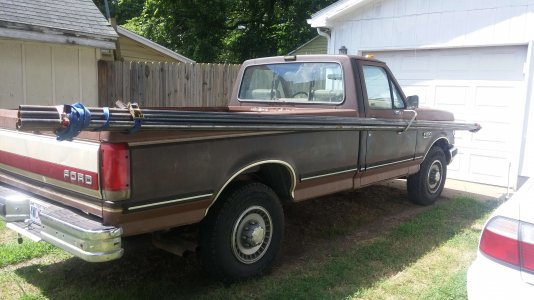
PSZfooP.jpeg

Stripped the truck down to a bare cab, frame, engine, and trans. I cut out the fender wells for ease of access, and the rest of the fender structure will be deleted once the engine cage is in. A factory core support is staying though. After stripping the truck, the factory coil buckets and bumpstop strike pads were removed, and the holes were filled.
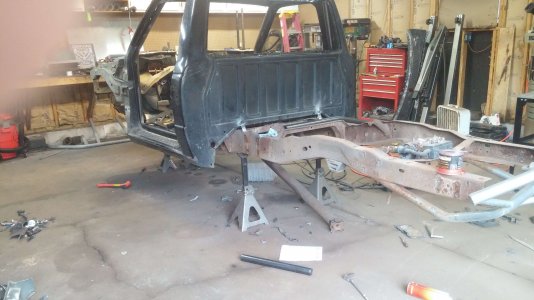
XjfdDMF.jpeg
Qr0zuNb.jpeg

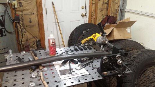
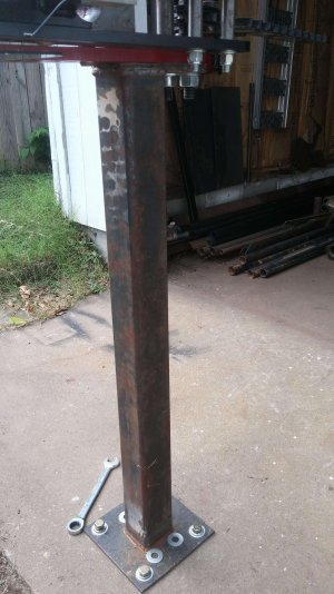
All past bending was done with the glorious Harbor Freight kinker, and notching was covered with the trusty old angle grinder. Picked up a Buildpro notcher, chintzy Klutch welding/fixture table, and a Pro-Tools 105 tubing bender. Welded up a quick stand for the bender instead of paying ~$160 shipped for one. Welding is far from great, but still considered pretty damn solid out here in sister-lover country.
6gEFBqR.jpeg
tntaPXM.jpeg

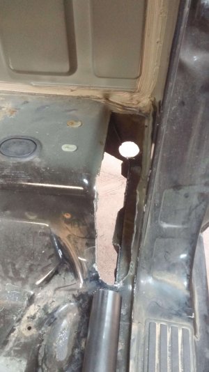
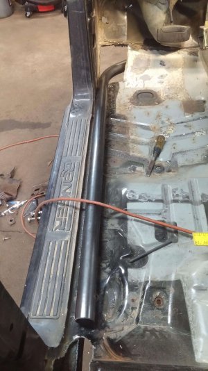
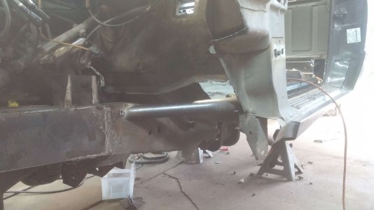
Huge props to @FasterNU for the PAD notes. They were obviously written for extended cab trucks from the previous generation, but a ton of info still crossed over perfectly. I hacked out the cab floors and set up the floor bars.
Pcl5v6T.jpeg
bRWaIdu.jpeg
v6L8x2S.jpeg
 
Then came the roof hacking and the A-pillar setup.
tkKI3PO.jpeg
tTMrsjc.jpeg
d9r6Yiz.jpeg
Yr0eczH.jpeg

I was dead set on keeping both wipers fully functional, while also properly tying the engine and cab cages together. The outermost tubes that intersect the A-pillars would be no big deal, but the rest of the cowl panel is a mess of computer/wipers/wiper motor/brake booster. I eventually decided to remove the cowl panel to get a better look for tube layout.
hSCrjPC.jpeg

OH YEAH, this showed me a way to tie the windshield A tubes into the engine cross-member, while also keeping the wipers functional. With everything still being tighter than your first girlfriend, I had to cut the corner out of the computer mount and remove one of the mounting tabs/bolts for the wiper motor plate. This got the tubes in place, but the wiper linkage was still rubbing hard on the passenger side. After some more hacking and reinforcement, the modified linkage clears with no issues. Due to the tight proximity to the hood and the computer on the passenger side, I had to make up some asymmetrical plates for bolting the crossmember to the firewall tubes. I made the fixed plates from 1/4" and tapped them for 7/16 fine bolts as a bit of an experiment. If/when the threads pull out, I can always throw a nut on the back side.
kdhUoM7.jpeg
eZrbEvC.jpeg
EZ2LLHh.jpeg
18U2fOp.jpeg
bfFE35e.jpeg
 
Bent up and notched the b-pillar bars. Two more that fit perfectly from FasterNU's PAD notes, even if they aren't exactly in the same place.
MyDX77V.jpeg
esRm63w.jpeg

Today's job was hacking up the floor with the Chinese plasma cutter and setting up the seat tubes. All 1.75" still, since that's the only die set I own, not counting the HF kinkmaster. I decided to tie the front tube into the frame like the b-pillar cross bar from the PAD cage. This will get tied into the door bar structure later.
xZkGsUV.jpeg
UbVDM1I.jpeg

The teardown started on Friday night, and I took this week off to bang out the cab cage at the very least. After that, it's back to mostly weekend work. Up next is the dash bar, roof bars, and the rear crossbar/diagonals. I'll start with the basic FasterNU PAD cage design like this.
1V2OVhB.jpeg

After the roof bar, I bent up the dash bar and the rear horizontal bar and notched them to fit. I can't actually install the dash bar until I cut the roof off and pull out the A-pillar/floor bar assemblies due to the way it's going to be tucked under the cowl panel lip.
TJVRtIR.jpeg
28W6Bp5.jpeg

After those tubes, I made the remaining holes for the outboard firewall tubes that connect the A-pillars to the engine cage.
bZtnIkv.jpeg

Dana 44 hubs and 9 inch meant swapping to 5x5.5 wheels, and since the BTF spindle is designed around a 2000 Expedition caliper, that meant upgrading to something larger than a 15" wheel. I had planned on keeping the existing 33s, but the larger wheels meant replacing those as well. I picked up some basic Pro Comp 17" wheels to keep with the 90s class-8 truck theme.

I was a die hard General Grabber AT2 guy, but they're retiring that line sadly. Since it was time to try something new, I picked up a set of Gladiator 35x12.5x17 all-terrains. The tread pattern/depth seems decent, reviews are solid, and they were an excellent deal. The BFG AT is a great tire, but they seem a little TOO proud of it, and the price reflects that.
JVrMjeb.jpeg

The front coilovers arrived as well, so the front suspension/engine cage mockup can begin as soon as I finish up the main cage.
je8ph5w.jpeg
 
Hacked off the roof and pulled the a-pillar/floor bar/b-pillar assemblies for finish welding/prep.
jyGtY7b.jpeg
Bxhw3Jd.jpeg

After lots of bashing and mangling the driver's side dash mounting points, managed to fit the assemblies back in with the dash/seat bars. Getting all of this to fit was a pain in the ass and a half, but the dash bar ended up tucked under the cowl nicely. Hopefully this will help minimize the dash/defroster hacking.
f1LxU1c.jpeg
uTpJ0jk.jpeg

Finish welded the rest of the floor/door sill bars, seat bars, rear b-pillars, roof bars, and rear horizontal bar. Welded a few bits of the body to the now-permanent cage structure and hacked out the rear cab mounts/floor to prep for the remaining rear tubes.
AfAWwPl.jpeg
nY3V32T.jpeg

I'll need to remove the crossmember behind the cab for upper link clearance, but this leaves me questioning the plan for the rear frame rails. Once I remove all of those crossmember rivets, the rear half of the frame falls off along with it.
kZpizDc.jpeg
I had planned on keeping the stock frame rails and just notching them for bump clearance, but now I'll have to actually re-attach the back half of the frame in order to keep it. I hadn't planned on backhalfing the truck, but it almost seems simpler to just do away with the frame rails in this case...

Decisions, decisions
 
16 rivets later, the rear frame half and after-cab crossmember are deleted.
fnUXTKx.jpeg

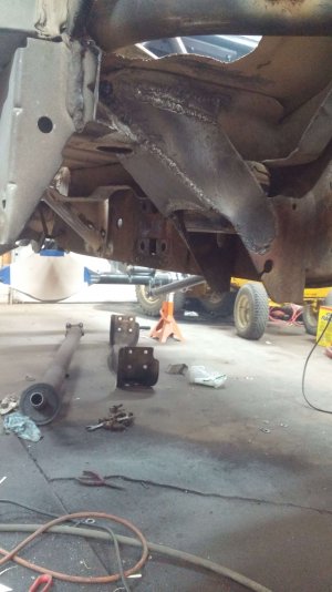
I found severe rust in the area where the two frame halves overlapped. Both frame rails looked normal from the outside, but both halves had been thinned to 1/16" or less. You can see the huge rust flakes sitting on top that had been between the plates. I probably would have folded this thing in half with a few more years of beating on the leaf springs. The rust made the decision for me. Backhalf is a go.
rDXB85P.jpeg

Finished cutting/grinding off the rear cab mount leftovers. Then notched and fitted the remaining six rear tubes.
G4XZDDl.jpeg
prJpDw3.jpeg

Apart from the flux residue I haven't fully cleaned off here, I think the welds are looking halfway decent. Landed the outer diagonals off the corner of the frame as well. Pulled the roof again afterward and finish welded everything.
mGXfTat.jpeg
ej598cA.jpeg
8rM65Jy.jpeg

Got back to the garage this weekend and started with finishing up the center through-firewall tubes and fittings.
TUDFKu5.jpeg
 
Local shop destroyed my Econoline 9" housing trying to "straighten" it. I ordered a basic semi-float housing to keep the project rolling. Very simple with 3" .3125 DOM tubes, .25" center sheet metal, rear truss, and Moser 35 spline axles (68" wms to wms). Also on the plus side, this housing has the diff centered which simplifies link mounting a tiny bit.
20201014_154508.jpg

Also picked up some PRP Comp Pro seats so I can finish up the cab cagework. Had paused the roof work previously since I had no reference for head/helmet clearance.
20201014_154557-min.jpg

I had built an earlier engine cage but hated it. Ripped it out and started over. Even V2 has plenty of compromises I'm not thrilled about, but it is a definite improvement over V1. I'll be cutting out the center cross tube to make it a bolt-in as well down the road.
20201025_185631-min (1).jpg
20201025_185742.jpg

I still have a few tubes left, but the bulk of the engine cage is complete. Now my primary issue is with the bump stop placement. Due to the short UCAs and the angles involved, the upper uniball/UCA surface is pointed straight at the master cylinder and the AC receiver/drier assembly at full bump. I could pick up a cantilever kit for the master cylinder, but I don't know of a great way to relocate the AC receiver/drier setup.
20201025_185405-min (1).jpg
20201025_185534-min (1).jpg

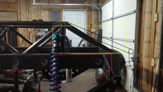
Started burning in the engine cage and mocked up the coilovers. I ended up having to mount the coilovers near the middle of the UCA window, due to the AC compressor/lines on the driver's side. I mounted the passenger side in the same fore/aft position just to keep things symmetrical, though there are no forward obstructions on the passenger side. If/when I add bypasses in the future, I'll need to modify the AC lines/receiver dryer assembly and then re-mount the coilovers further forward.
20201101_183135.jpg

Got the passenger side coilover solidly mounted afterward. Modified the AC receiver/dryer mounting brackets and "massaged" it slightly with a mallet to suck it in closer to the heater box for coilover clearance. If/when bypasses happen in the future, I'll have to do some serious AC system modifications to fit them.
20201101_183227.jpg
20201101_205324-MR.jpg
I started at 17.5" of travel, but I sacrificed 1.5" of downtravel to get the motion ratio as close to correct as possible. I didn't manage to quite get 90 degrees at full bump, but it's close. In the end, I finished with 16" of travel on both sides metal to metal. I'm plenty happy with that.
 
Made some proper tabs for the LCA side to start, then made the corresponding upper C/O mount for the driver's side. Added diagonals to support the upper C/O mounts as well.

20201102_175136-min (1).jpg
20201102_175024.jpg
20201102_175048.jpg
20201102_175006-min (1).jpg

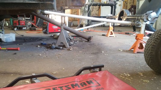
Since the wheelbase on a short bed single cab Ranger is on the short side at ~112", I figured I would stretch the wheelbase to ~118" and use long bed glass instead. My link material is 48" 2.5" .25 wall DOM. I made some mockup lower links with PVC and set them at a total length of 54" center to center. I tacked the tabs to the bottom of the housing 47.5" apart and with their front edges at 0 degrees to the housing face.
20201105_160817.jpg
From what I've read, you want the lower link pivot roughly inline with the front u joint to minimize driveshaft plunge. Even with my longer than normal 54" links, the front pivot is still ~14" rearward of the front u-joint.
20201105_160842.jpg
This concerned me a bit, but then I realized that there are plenty of single cab, 48" linked, one piece driveshaft Rangers running around with no issues. My axle is 6" further rearward, and their links are 6" shorter. Either way, we're in the same boat.

Mounted the upper link tabs, trimmed the frame crossmember, and trimmed the upper link pivots to maximize the vertical link spread in the front. Mounted everything with the mock-up links and started cycling to check the basics. I wasn't able to check full droop with the chassis sitting at ride height, but I ended up with ~7 degrees of pinion angle change and ~1/2" of driveshaft plunge over 22" of travel. Should be able to check full droop once I get the backhalf put together.
20201106_152244-min (1).jpg
20201106_151209-min (1).jpg
20201106_151531-min (1).jpg

After getting everything dialed in, I prepped the link tubes and tacked everything together. Cycled things a few more times and adjusted where needed.
20201106_175953-min (1).jpg

Final wheelbase is 119" with long bed axle positioning and the BTF kit kicking the front wheels 1" forward. All things considered, I think I got very lucky with this setup. I took a guess at 54" lower links and 48" upper links, and everything just happened to work out great. Plugged my numbers into the 4 link calculator afterward and came up with 62% anti-squat. Not bad, but I would have liked to get this under 50%. The frame rails limit the upper link mount positioning, and I didn't want the lower link mounts hanging way under the chassis, so I guess I'll live with it. Apart from that, I'm very happy with how things turned out. Minimal plunge, minimal pinion angle change, and half-decent squat numbers.
 
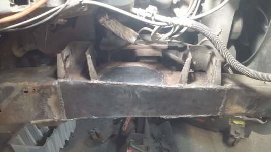
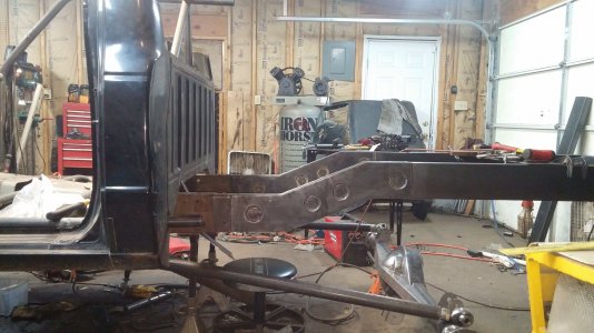
Since I'm essentially copying a 90s class 8 truck, I decided to recreate the rear half of the frame with new material. 2x6 rectangular tubing fits perfectly inside of the stock frame rails, and a couple of pie cuts gave me a 6" frame kick for bump clearance.
20201114_181745 (1).jpg

With the rear at full bump, this puts the bottom edge of the wheels ~1/2" higher than the cab frame rails. I figured I would stop there instead of worrying about the frame rails slamming into the ground and compressing my spine.
20201114_181725 (1).jpg

Cleaned up the stock frame rail stubs and slid the new rails into place. After aligning/squaring/leveling everything, I went ahead and got them ~90% burned in. Now that everything is probably warped to hell, I'll realign the frame rails again and throw in some temporary cross bracing while I build the rest of the backhalf.
20201118_011049-min (1).jpg

Got the frame squared up again and welded in the rear crossmember. Then I cut out the inner and outer frame kick overlay plates. Went with 3/16" for the outside, and 1/8" inside. Found out that hole sawing 2.75" holes in 3/16" plate with a wimpy drill press is absolute hell. 8 holes down, and about 30 more of the fuckin things to go sadly. Makes the loudest screeching imaginable. Neighbors get to hear about 3 more hours of it tomorrow.
20201121_193336 (1).jpg

Finished hole sawing the frame kick plates, cleaned them up, and burned them in.
20201122_182400-min (1).jpg

Fixed up the drill press and finished hole sawing the frame overlay plates. I had measured everything out to ensure that the holes lined up, but I'm apparently brain damaged and welded the driver's side on backward. So the first two holes along the seam are too close together. Was sure as hell not going to cut the plate off for a minor cosmetic issue though, and just welded up the passenger side to match.
20201126_173414 (1).jpg
20201126_173358-min (1).jpg

Spent a day and a half figuring out why the four link was doing weird shit. From full bump to 3/4 droop, the axle was moving ~1.5" horizontally. After triple checking everything, I finally figured out that my passenger upper link mount on the chassis was 1/4 further forward than the driver's side. I found that the passenger lower link mount on the chassis side was also 1/16" rearward from the driver's side. After correcting both of those issues and squaring everything up again, I'm down to ~3/16" of horizontal movement over 22" of travel. Not perfect, but close enough that I don't really need to worry about it anymore. After that I welded on the axle-side tabs for good.
20201201_172835 (1).jpg
20201201_172852 (1).jpg

After finally getting the four link more or less finished, I decided I needed to mock up the mezzanine arms before building the bed cage. The upper coilover mounts determine the location of the bed cage down tubes, so I need to figure out the coilover position first. Step one was to build the axle side mezzanine arm links/pivots. While the chassis tubing is HREW, I'm using DOM tubing for all of the suspension components. With these done, I can work on the mezzanine arms themselves tomorrow.
20201201_172740 (1).jpg
 
Cut out/dimpled the components for the passenger rear mezzanine arm mount, and then I went ahead and plated the top of the frame rails to prep for the bed cage. Hole sawed the cab to meet the cage, and cut out/notched the first four bed cage tubes.
20201203_194748 (1).jpg

Got the bulk of the bed cage diagonals done, with just the two going into the cab left to do. Those will take some careful sheet metal trimming. I'll be leaving the rear unfinished until I decide what to do with the spares, but I can go ahead and work on the mezzanine arms/shock positioning with the main bed cage structure tacked together.
20201204_174325 (1).jpg

After a few more revisions, I decided on a final mezzanine arm design. Did some half-assed mockup with the 10" coilovers borrowed from the front, but I'll likely wait until I've got some 14" coilovers in hand to finalize the coilover mount/side plates. The front heim mount area needs some clearancing for better articulation, but everything travels well otherwise.
20201213_183813-min (1).jpg

Figured out the coilover positioning and continued working on the mezzanine arms. Burned in the main tubes and cut out the rest of the side plates. Bypass rod end is very tight at full bump, but has lots of room otherwise. I don't expect to see extreme articulation with one end of the axle at full bump anyway, so probably a non-issue. Still have to add four more dimples+connecting tubes in the middle section, but I'll likely be leaving the "hook" portion solid.
20201219_172132ps.jpg

Finished drilling/dimpling the side plates for both arms and then cut out and welded the shock pocket inserts. Had to clearance the side to clear the side plate dimples, but these holes will basically turn into big plug welds anyway during final install.
20201220_173653-min (1).jpg
20201220_173127-min (1).jpg

Clears King 2.5 rod ends with no issues, but it is very tight. Zero chance of anything with a larger rod end fitting in here.
20201220_173721 (1).jpg

Started cutting out the tubes that connect the two dimpled sides. These things are are surprisingly annoying to make just because they're so damn short. Only have to make 22 more of them.
20201220_173946 (1).jpg

Got a bit more fab time in and welded the shock pockets into the main bodies of the mezzanine arms. Clearanced the side plates around the axle-side heim for improved articulation, and then welded them in for good.
20201224_163533 (1).jpg
20201224_185415 (1).jpg
 
The flux-core hellhole that is the inside of the shock pockets reminded me once again to stop being a lazy fuck and buy some welding gas.
20201224_185303-min (1).jpg

Finally warmed back up a bit here as well, so I finished welding up the other mezzanine arm on Sunday. Still covered in flux core bird shit like the other, but I can finally clean them both up and throw some primer on them tonight now that the cold is gone.
20210125_122608-min.jpg

Still too cold to fab anything, but the 9 inch center finally came in. Ended up going with a Strange nodular housing/pinion support, 4.86 gears, and a Detroit/Eaton TrueTrac. Should move the truck fairly well with ~300 HP and 35s. Can finally get some measurements for the driveshaft shop as well.
20210217_131725.jpg

Spent half a day figuring out the rear mezzanine arm mounts and got one side mostly tacked together. Used 2x2 square tube to make a pocket for nut access.
20210227_173610 (1).jpg
20210227_173640 (1).jpg
20210228_190029 (1).jpg
20210228_190307 (1).jpg
20210228_190116 (1).jpg

Got the main bed cage structure completed and fully welded. Now that the frame is rigid, I think I'll fab up some proper jackstands tomorrow to make this project a bit safer. You can see my current solution is a pair of sketchy recalled Harbor Freight jackstands at max extension with 4x4 tubing spacers on top. Better fix that before I kill myself.
20210306_185930 (1).jpg
 
Thanks dude for helping out with posting up your build thread! Truck is going to be rad when it's back out in the dirt!
 
Pulled the core support, engine, and trans to start. I knew the engine was leaking, but I found out the thing was pissing oil from the front main, rear main, and the front of the lower intake. Caked in oil front to back. I've never had good luck keeping the leaks away with Ford small blocks.
20210314_172243 (1).jpg

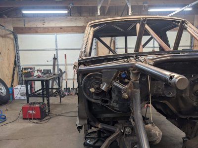
With the engine bay clear, I finished the removable cross-tube and finished welding the rest of the engine cage. Engine cage still needs a few gussets and the downtubes from the outer "wings" to be 100% complete.
20210314_172318 (1).jpg

Marked the crossmember around the oil pan before pulling the engine, but I decided to go big and guarantee that I'd have tons of clearance for this engine (and possibly future engines). Once that was all plasma'd out, I plated the crossmember back in.
20210314_164352-min (1).jpg
20210314_172018 (1).jpg

Got a couple of free hours after work and got the passenger mezzanine arm tacked in place. Picked up some used Fox 2.5 triple bypasses as well that should be here by next weekend. Then I can make some half-ass shock mounts and do some cycling/clearancing.
20210315_214658.jpg

With the rear mostly intact minus MIA shocks, I decided to finally fab up the tie rods. They're just plain .120 wall 1.5" DOM with 3/4" inner and 7/8" outer heims. Now I can do some proper cycling on the front as well and do a half-assed alignment.
20210315_214725.jpg

Drilled the necessary hole, and then welded up the differential fill bung and upper link mount reinforcement plate.
20210316_215107.jpg

Fabbed and welded the four roof corner gussets in the cab afterward. Just need to fab the roof diagonals and I can slip the cab roof back on, which lets me finish up the bed cage as well. It's all coming together a few tubes at a time.
20210316_215048.jpg

Fabbed and welded up the three roof bars and the rear vertical tube. I still have to wrap up a few things under the cab, but the main cage is basically complete.
20210317_212537.jpg
 
Welded in the outrigger tubes for the engine cage "wings" and then threw some taco gussets on both of those and under the engine cross bar. I was hoping to get both sides symmetrical, but the driver's side of the cab actually juts out further forward than the passenger side (I assume for pedal clearance). Driver's side tube ends up ~1.75" further forward. Eh, close enough I guess
20210321_172602.jpg
20210321_172648.jpg

Fabbed up the frame outrigger things under the main seat tube and plated them in. Made everything extra tight so I could still weld the factory floor supports in place. Just to make the floor a bit more rigid, as it has been plenty floppy for a while now.
20210321_172812.jpg
20210321_172848.jpg

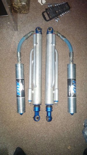
Picked up some used Fox 2.5x16 triple bypasses. They're the oldschool style with the resis coming out of the wrong end, but I couldn't pass up a deal.
20210321_180816.jpg

Got the roof reinstalled and fully welded without banging up the cage paint too badly.

20210325_222516.jpg

To reinforce the A-pillar area, I sank two pieces of 3x3 square tubing through slots in the floor that straddled the existing cab floor box section. I then plated this to the frame-side cab mount and boxed in the bottom side.
20210402_194222.jpg
20210402_194756.jpg

Couldn't find any decent screw-type jacks locally, so I decided to go ahead and make a pair of jack stands. 3" .188 wall outer tube with a 2.5" .120 wall inner tube drilled in 1" increments. 3/16" base plate with 1" square tube diagonals. 27" collapsed and 42" fully extended.
20210405_213152.jpg
 

Attachments

  • 20210404_211459plan.jpg
    20210404_211459plan.jpg
    516.9 KB · Views: 2
After reading dozens of "why didn't I do this earlier?" posts from people who moved mid-mounted fuel cells to the rear, I'm pretty damn certain I'll be doing the same. This means ditching the dual spares and hacking off the rearmost bedcage diagonals in favor of a rear cell with a single flat mounted spare. Shitty MS paint pictures for reference. Tire and cell outlines are pretty close to scale, and the green line is roughly the rear plane of the longbed bedsides.
20210404_211459plan.jpg
20210404_205400plan.jpg
Did a TON of cycling and adjusting in the rear and got the four link and mezzanine arms dialed in. Axle links invert at ~27.5" from the frame, and at ~26.5" with extreme articulation. I'll strap the rear at 25" to be safe, but I'm pretty happy with how things worked out. I could make the axle links longer and move the pivots lower to get a couple more inches of droop travel, but meh. I'm good with it as is.
20210406_183513.jpg

This is the max articulation before mezzanine arms start twisting and potentially tacoing shock shafts. Not too terrible. I'm probably fine with bypasses+bumps, but I'm guessing I should probably add a sway bar for some extra safety.
20210406_183938.jpg

After getting the rear dialed, I went ahead and mounted the rear bumps and strike pads.20210406_222001.jpg
20210406_222014.jpg

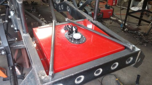
Threw together the fuel cell mount. Don't mind the giant spill in the back. I definitely DIDN'T kick the tailshaft plug out of the trans.
20210408_211549-min (1).jpg
20210410_185136.jpg
20210411_172233.jpg
20210411_172024.jpg
 
Spent a few hours in the garage and threw two diagonals into the fuel cell carrier. Then I added two tubes to brace the engine cage outriggers/A pillar area.20210412_164232.jpg
20210412_164827.jpg

Added the last two horizontal tubes at the base of the B pillar, and the cab cage is pretty much complete. Started the sheet metal work afterward. Holes all patched with 16 gauge plate.
20210414_190243-min (1).jpg
20210414_190420.jpg
20210414_190401-min (1).jpg

Finished the floor and trans tunnel patches.
20210415_172039.jpg

Threw together some dimpled B-pillar to cab plates, and then notched some door bars. I'll likely add another bar to make a proper X later, but I'll need the dash in place first to check clearances.
20210416_182736.jpg
20210416_182716.jpg

After replacing the melted wiper linkage bushings, I welded the cowl panel back in place as well. Fingers crossed I don't have any weird windshield install issues later.
20210416_182615-min (1).jpg
 
Made some dimpled A pillar gussets and got them welded up.
20210417_183650.jpg

After that, I made a base for the fuel cell out of angle iron to locate it since there was a bit of play in the carrier itself. Then I started working on the topside of the fuel cell retainer. Topside of the frame was just drilled and tapped for 1/2" bolts. Not a lot of threads, but I'll nutsert it if it ever becomes an issue.
20210417_183749.jpg
20210417_183721.jpg

Finished fabbing the fuel cell retainer and mounted the filler neck as well. Makes the filler accessible to a typical gas pump, and the supports prevent me from smashing the fuel fittings with the spare.
20210418_192443.jpg
20210418_192654.jpg

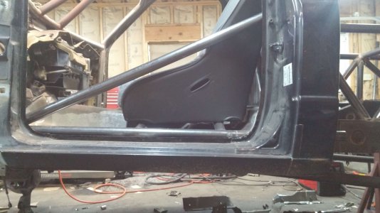
Threw the seats back in the truck to check the fitment and realized that I'll need to make some changes. I clear the roof tubes no problem without a helmet, but I'll be banging tubes all day long with a helmet on. You can see that the seat is actually pitched forward a bit. The rear seat tube sits about a 1/2" higher than the forward seat tube.
20210420_204430.jpg

Chopped out the rear seat tube and gave the floor the old gape job with the plasma. The new 1.5" tube is actually sitting on top of the frame rails, and I'll have to tweak the ends of the tube ever so slightly before welding to close the remaining 1/8" gap. I'll lower the rear corner sheet metal of the floor a bit as well so I don't have to crawl under the truck to install 1 out of 4 bolts.20210421_205614.jpg
20210421_205502.jpg
Rear of the seat dropped ~2 inches, and I've got ~1.5" of head to tube clearance all around with a helmet on. Once I'm belted in and I've broken in the seats a bit, shouldn't have to think about it again. Well worth re-doing the tube and some floor pan modification.

Finished lowering the rear of the cab floor, which leaves the frame rails poking into the cab a bit. Welded up the remaining random holes in the cab as well. Cab floor is a patchwork mess. I definitely see why people just cut the floor out entirely and fill it back in later.
20210424_183652-min (1).jpg
 
Minor update, but 3/9 water pump bolts had been broken since I got the engine. It wasn't leaking, so I hadn't bothered to fix it during the swap. The outermost bolt shanks were seized absolutely solid in the timing cover. After heating and beating failed, I persuaded the cover to release via an angle grinder.
PXL_20211202_030929718-min.jpg

Cleaned up the cover afterward, and every new bolt will get slathered liberally with anti-seize. Outer holes aren't fully supported, but I see no real issue considering there was no bolt present at all for years.
PXL_20211206_002316756-min (1).jpg

Spent a ton of time eyeballing the front bumps, and finally tacked them in a position I think will work. I'll still need to extend a bump pad off of the edge of the UCA, but this was as good as I could get it with the air conditioning receiver/dryer in the way. Driver's side has a ton of room, but I'll make them symmetrical regardless.
PXL_20211209_021045086 (1).jpg
PXL_20211209_021140201 (1).jpg
I know the goal is to have the strike surface 90 degrees to the bump stop halfway through its stroke, but this is as close as the packaging lets me get. I could bump off of the LCA, but I assume the above setup is still preferable.

Threw together one of the bump mounts after work. Started trying to cope a tube at first, but the compound angles and notches made it complete AIDS. Ditched that, did some cardboard aided design, and made it out of plate instead.
PXL_20211210_042926365 (1).jpg
PXL_20211210_042859508-edit.jpg

I knew the rear tire carrier tube would be a bitch, so I'd been putting it off for quite a while. Bent it up in sections, since laying out continuous bends is still magic to me.
PXL_20211211_190913092 (1).jpg
PXL_20211211_224315232 (1).jpg
 

Attachments

  • PXL_20211209_021045086 (1).jpg
    PXL_20211209_021045086 (1).jpg
    292.9 KB · Views: 1
  • PXL_20211209_021140201 (1).jpg
    PXL_20211209_021140201 (1).jpg
    288.6 KB · Views: 1
Wrapped up the rear bumper/tire carrier.
PXL_20211213_043246283 (1).jpg

Mounted the driver's bump up front, fully welded both, and added tube braces. Master cylinder slips in and out without too much hassle.
PXL_20211213_043053285.MP (1).jpg
PXL_20211213_043126397 (1).jpg
PXL_20211213_043113690 (1).jpg

Picked up one of those chintzy mini-lathes for shits and giggles. Couldn't say no at $450. Tore it apart, deburred everything, cleaned out the metal shavings, and got the ways tightened up.
PXL_20211214_054714342.jpg
Picked up a chunk of 3.5" T6 and decided I'd figure out how to make some D44 hub caps.

Figured out the angles and such to get a decent finish on these part blanks. Then came time to cut them off the bar stock...
PXL_20211215_040404881 (1).jpg
(Note to self, buy a porta-band. Hacksawing through 3.5" aluminum bar sucks dick.)

Since the little lathe could only really handle 0.005-0.010 passes, turning one cap took 5 hours. Had a bit of chatter in the root of the inner chamfer, but pretty pleased overall for my first go at things.
PXL_20211216_062524296 (1).jpg
PXL_20211216_062613522 (1).jpg

Finished up the hub covers. Finish improved quite a bit when I ditched the Chinese carbide for HSS. Just waiting on some snap rings from McMaster Carr to get them installed. There's probably a proper tool for drilling flat-bottomed countersunk holes, but careful drilling with a 7/16" endmill in the drill press did a decent job.
PXL_20211218_214517937 (1).jpg
PXL_20211218_214533899 (1).jpg
 
Back
Top