88’ Raingutter Ranger

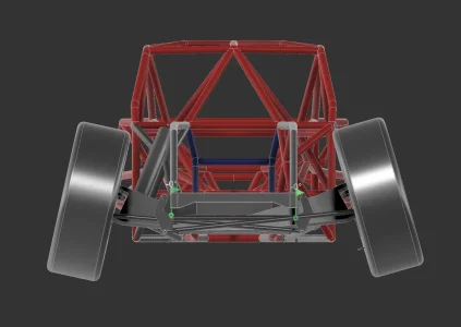
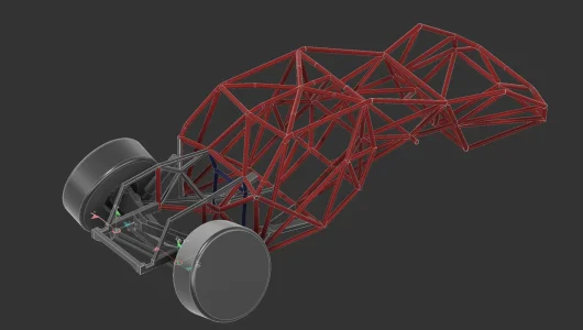
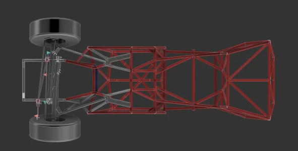
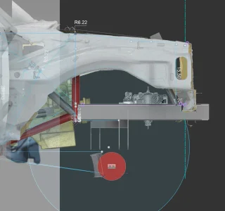
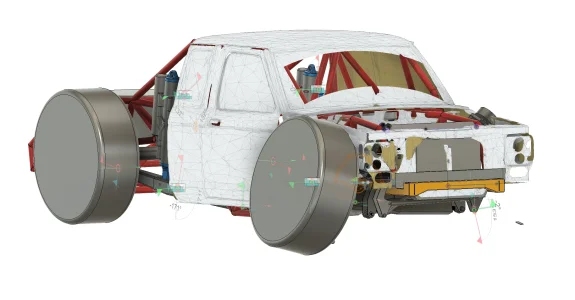
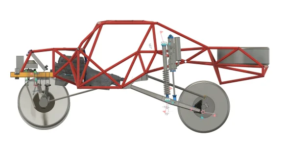
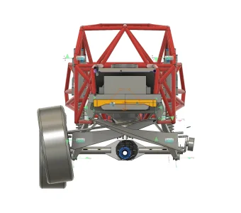
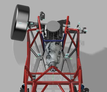
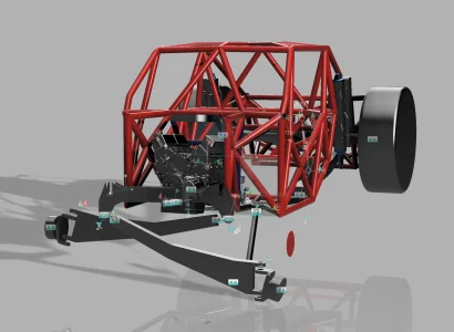
With the drivetrain placed damn near close, I spent the rest of the day locating my radius arm mounts. Kept them as long and near center as I could while keeping the middle open for ease in removing the transmission for service. Planning on finalizing/cleaning up the plate work on it in a few days. Other than adding a few more tubes to the engine bay, will do one more look over on tube interferences and send the chassis off to laser.

Been chipping at this project for the last 5 years, definitely itching to put this puzzle together. Given I already have most of the suspension/drivetrain ready, would like to see this thing rolling relatively shortly after starting. Appreciate all the help from everyone along the way.
 

Attachments

  • Screenshot 2026-01-03 at 7.50.09 PM.webp
    Screenshot 2026-01-03 at 7.50.09 PM.webp
    163.2 KB · Views: 48
  • Screenshot 2026-01-03 at 7.51.35 PM.webp
    Screenshot 2026-01-03 at 7.51.35 PM.webp
    159.3 KB · Views: 43
We are getting close! From Main Cab to Fuel Cell Carrier, tubes have all been normalized and got quotes back for. Working on the front frame/suspension components and currently stuck on the Motor Plate. Looking to do 3/8inch aluminum machined plate, does anyone have experience installing one? I can only find them installed but no one talks about any modifications for the engine or transmission to work with the added gap between the two. Thanks!
I'm running a 3/8 plate on mine. It's plenty strong enough. Same size Camburg runs on their TTs... You don't run the normal motor mounts with them however. You'll need a front mount to the motor as well. That way when you pull the motor you're only unbolting it from the mid plate then fully removing the front plate allowing your motor to slide forward and out. Whatever your spacing for the midplate is, you will add to your torque convertor mounts.
 
I'm running a 3/8 plate on mine. It's plenty strong enough. Same size Camburg runs on their TTs... You don't run the normal motor mounts with them however. You'll need a front mount to the motor as well. That way when you pull the motor you're only unbolting it from the mid plate then fully removing the front plate allowing your motor to slide forward and out. Whatever your spacing for the midplate is, you will add to your torque convertor mounts.
Rad thanks Dave. By chance are you able to tell me what your horizontal and vertical spacing was for your pivot boxes at the frame?
 
Last edited:
That all depends on what you want to do with antisquat numbers to be honest. All changes depending on what you're looking for
Yea was just looking for something to compare to, just feel like my vertical and horizontals are more than what I see on others
 
Yea was just looking for something to compare to, just feel like my vertical and horizontals are more than what I see on others
Comparing apples to oranges to cucumbers over here, but:

the last few trucks I’ve linked were 11” vertical separation at the axle

7” vertical separation at the frame
Upper link pivot 7” aft of lower link pivot
 
Just about ready to send the chassis off to laser. Spent the last few days altering the frame rails to accept the stock front core support, finalizing the beam mounts/swinger geometry, and fitting coolers/radiators in the massive hole where my engine used to be. Have a few small items to hit like locating the steering box, small changes to the engine cage, and possibly one more geometry change to the rear to move the lower link pivot closer to the transmission output. Went on Ebay/LMC and bought a Lund Cab Visor and a stock chrome bumper, goal is to keep it "vintage" (absolutely no Raptor glass :sick:) Can't wait to get this on a table!
 

Attachments

  • Screenshot 2026-01-27 at 11.04.15 AM.webp
    Screenshot 2026-01-27 at 11.04.15 AM.webp
    66.7 KB · Views: 20
  • Screenshot 2026-01-27 at 11.05.53 AM.webp
    Screenshot 2026-01-27 at 11.05.53 AM.webp
    144 KB · Views: 18
  • Screenshot 2026-01-27 at 11.06.10 AM.webp
    Screenshot 2026-01-27 at 11.06.10 AM.webp
    102.5 KB · Views: 23
  • Screenshot 2026-01-27 at 11.08.41 AM.webp
    Screenshot 2026-01-27 at 11.08.41 AM.webp
    107.6 KB · Views: 29
  • Screenshot 2026-01-27 at 11.15.42 AM.webp
    Screenshot 2026-01-27 at 11.15.42 AM.webp
    57.1 KB · Views: 40
Been sitting on this most the day, looking for some input. To fit the radiator I either have to ditch the core support (already has 2 coolers mounted in it, headlights, and lets me easily locate in "space" where my fenders and hood mount to) or move it to the back of the truck (probably will still have front/rear windshield, have to plumb it all the way to the rear which I was trying to avoid). Any thoughts?
 
What a trip it has been designing something from the ground up. It is definitely surreal to see something that has taken years come to fruition, and it hasn't even hit a chassis table yet. Thank you to everyone who has given input into the build and the help along the way, I really appreciate it. Got a stock bumper in the mail today and man does it look good, excited to get this thing rolling. Just some cleanup on the files and maybe some minor alterations if someone gives me insight before hand, but will be sending this off to laser shortly. I'll include the quotes when its done for anyone who wants some idea of what it costs to have a chassis cut and bent.

Just some numbers to put out there for anyone else to use or compare to
- Front frame moved up about 4" and will have an additional 2" notch in them
- Beam Pivots have a 7" separation with a 6" drop. Both steering swingers are 8.5" forward of each beam pivot mount
- Attempting to run 16" coil in the front (eventually bypass), 24" of travel metal to metal
- Ran the radius arms as long as possible, at 43" overall length
- Transmission output is sitting 4.85" above the rear link pivot, will have 1.7" of plunge.
- Have three adjustable upper link locations to change A/S. Rough since I don′t have exact CG but should be near 57%, 70%, and 84%
- Lower link pivots have a 13" horizontal spread, and starts at 5.5" vertical separation going up at 1.2" intervals for the additional upper link holes
- 60" lower links, 51" uppers. 16/18" shock combo getting 31" of travel metal to metal

If anyone needs any other specific numbers I will be happy to share. Below will be all the "finished" pics of the truck.
 

Attachments

  • Screenshot 2026-02-01 at 5.13.20 PM.webp
    Screenshot 2026-02-01 at 5.13.20 PM.webp
    171.1 KB · Views: 25
  • Screenshot 2026-02-01 at 5.12.03 PM.webp
    Screenshot 2026-02-01 at 5.12.03 PM.webp
    165 KB · Views: 23
  • Screenshot 2026-02-01 at 5.12.47 PM.webp
    Screenshot 2026-02-01 at 5.12.47 PM.webp
    141.6 KB · Views: 22
  • Screenshot 2026-02-01 at 5.09.47 PM.webp
    Screenshot 2026-02-01 at 5.09.47 PM.webp
    156.7 KB · Views: 23
  • Screenshot 2026-02-01 at 5.11.42 PM.webp
    Screenshot 2026-02-01 at 5.11.42 PM.webp
    178.7 KB · Views: 19
  • Screenshot 2026-02-01 at 5.11.53 PM.webp
    Screenshot 2026-02-01 at 5.11.53 PM.webp
    104.5 KB · Views: 19
Back
Top