99 XLT Ranger - Baja Betty

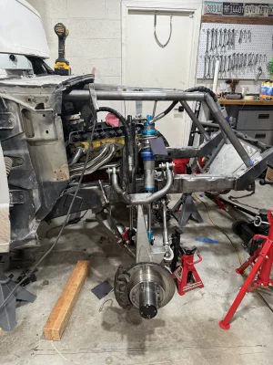
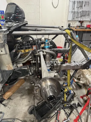
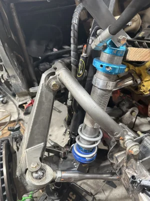
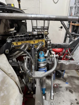
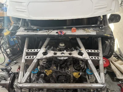
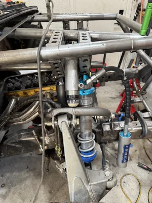
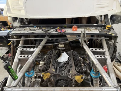
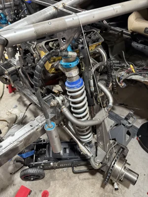
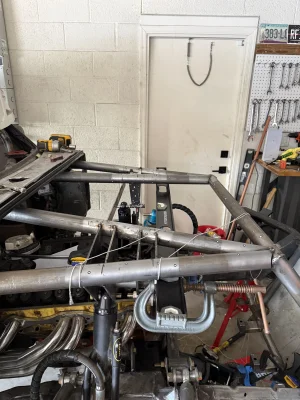
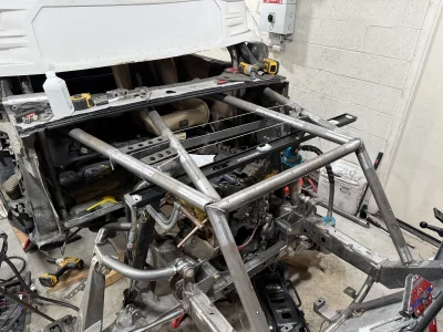
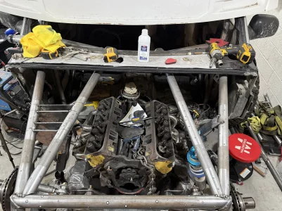
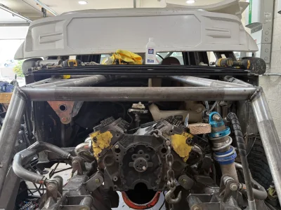
Chopped off the LCA shock mounts and reset the suspension at new full compression on passenger side. With a bit of playing with the arrangement im sitting around 16.5” of clean travel, aproximafley 50-50 down/up travel. Previously around 12” of travel, so the result should be a massive improvement.

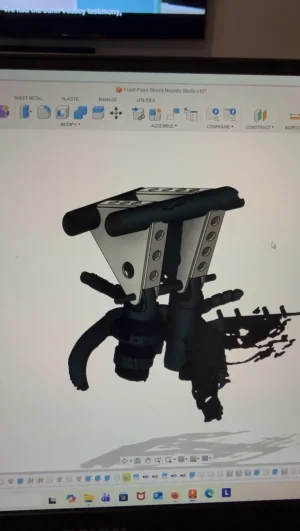
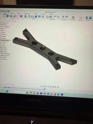
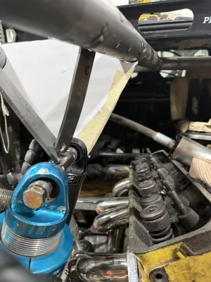
Now working on boxed shock mounts via cardboard aided design and replicating on drivers side. Then placing steering box in the chassis for the swing steer after I get an older model that has 1/2” bolts, instead of the 14mm version I currently have.
 

Attachments

  • IMG_0938.webp
    IMG_0938.webp
    2.5 MB · Views: 76
  • IMG_0929.webp
    IMG_0929.webp
    2.3 MB · Views: 47
  • IMG_0930.webp
    IMG_0930.webp
    1.4 MB · Views: 57
Decided to change things up a bit on the upper shock mounts and do a laser scan with the new Einstar 2 so I could CAD the mounts.

Pretty happy with the final result, I’ll have a bit of hand fitting to do but extremely happy with how it turned out. 1.25” DOM tube will go between shock towers to prevent bending. Going to cut later this week and then mock up before doing the drivers side.

Imgur link: CAD Model
 

Attachments

  • IMG_1025.webp
    IMG_1025.webp
    70.6 KB · Views: 35
Continued efforts on the shock mounts - have the passenger side location dialed in and working on matching drivers side. Have the scan and design completed and cutting out the plate this weekend for final tweaking to ensure good alignment between passenger/driver/ and a removable brace.
 

Attachments

  • IMG_1119.webp
    IMG_1119.webp
    2.1 MB · Views: 18
  • IMG_1127.webp
    IMG_1127.webp
    976.3 KB · Views: 24
Einstar 2 3d laser scanner has helped speed up my design and fabrication.

Have the shock mounts and crossover brace mocked up pending final weld and tab fitting.

Now working on bumpstop mounting and then back to finishing the steering before tubing out the remainder of the structure.
 

Attachments

  • IMG_1405.webp
    IMG_1405.webp
    1.7 MB · Views: 19
  • IMG_1348.webp
    IMG_1348.webp
    1.6 MB · Views: 14
  • IMG_1347.webp
    IMG_1347.webp
    1.9 MB · Views: 11
  • IMG_1251.webp
    IMG_1251.webp
    794.3 KB · Views: 11
  • IMG_1220.webp
    IMG_1220.webp
    403.1 KB · Views: 12
  • IMG_1191.webp
    IMG_1191.webp
    1.5 MB · Views: 11
  • IMG_1171.webp
    IMG_1171.webp
    1.4 MB · Views: 13
  • IMG_1161.webp
    IMG_1161.webp
    1.9 MB · Views: 11
  • IMG_1154.webp
    IMG_1154.webp
    1.6 MB · Views: 20
I’m sure you smart enough to cycle everything in real person before you welder up. While scanning and cad have come a tremendous amount of way, they just coke up short just like humans sometimes.

More than one occasions we’ve had trucks come into the shop with a “cad designed” part that worked perfectly in their calculator, but came up short in real life.

Either way, looking good!
Good question. I set the shocks at full bump and held in place with tabs and a .75x.120 tube and a bolt. Needed to be able to check for clearance at full extension on the coil over and bypass with the frame & upper arm/spindle. Checked for clean cycling at that point.

After confirming no clearance or cycling issues I scanned the tubes, shocks with pins sticking out to work from and removed the tabs in post process. Repeated for driver side a.

I then reconfirmed it’s cycling fine during mock up.
 

Attachments

  • IMG_1411.webp
    IMG_1411.webp
    53.8 KB · Views: 11
  • IMG_1127.webp
    IMG_1127.webp
    976.3 KB · Views: 13
  • IMG_0989.webp
    IMG_0989.webp
    1.1 MB · Views: 12
Back
Top