97 TTB Ranger

I finished the setting up the rear suspension. Getting 15-16” of travel with a 14” bypass. The bedcage bolts in with the stock front bed bolts and some 1/2 bolts right above the bump stops. I ended up shortening the wheel base in the back 1/2” and shortening the driveshaft 1.5”. I need to make a bumper mount, however the shackles are in the way. Might just box the frame and extend it.

Now i'm on to the cage design. All 2” dom with the red tubes being 0.125” wall and the green 0.095”. At this time I’m not planning on doing intrusion bars but i’ll see.
 

Attachments

  • IMG_4480.webp
    IMG_4480.webp
    542.2 KB · Views: 86
  • IMG_4579.webp
    IMG_4579.webp
    208.5 KB · Views: 56
  • IMG_4580.webp
    IMG_4580.webp
    283.1 KB · Views: 58
  • IMG_4595.webp
    IMG_4595.webp
    246.3 KB · Views: 66
  • IMG_4660.webp
    IMG_4660.webp
    243.7 KB · Views: 63
Last edited:
BADASS man. good fucking job so far! Keep it up!
jealous of the SW drawing skills. or w/e program that is. 3d edge or, i dont fucking know whats out there nowadays. hah
 
Thanks! and yeah its Solidworks.
(personal post, read if you want/dont, i dgaf hah)

Nice! i actually got an Associates Degree in Mechanical Drafting. we used AutoCAD at school and after i graduated i got a job using AutoCAD still and i was FUCKING PRO & FAST AS SHIT with that program. always wanted to learn and be good at SW though. now, i cant remember anything that was close to my death experience and just go off what people tell me but, my old boss says that i had actually been using SW a lot and i had gotten pretty good at it right before i decided to faceplant on a minivan. problem was..... then i fucking died. then i fucking forgot EVERYTHING. so i dont remember much of it anymore.
i mean, i use it at my current job and ive gotten OK with it (for the stuff we do at work at least, nothing else. hah). but ive always wanted to do exactly what youre posting pics of and be able to draw out a full cage inside a truck. problem 2 is, yoga has taken over my life and i dont have any desire to draw cool truck shit on SW anymore. i think i could have been a really good draftsman if, well.... if if if...... you know how that goes. hah

ok personal story over, back to truck pics and good SW drawings. haha
 
I have used urethane bushings for swinger pivots before and they work BUT i cut the hats off some and make the tube full of bushings from edge to edge to help with stiffness. Now I run Delrin because I needed new ones.
 
I took the ranger out to ocotillo for the morning to give the rear suspension a test. It worked much better but was still rough and a little unpredictable. It was jarring in the rear and the bump steer from the front seemed to get me sideways quite a lot in whoops. I haven’t done much to the bypasses but speed up the rebound. I think I need to open the short compression and close the long compression but I only have the weight of one spare which is likely the problem.
 

Attachments

I started on a roll cage and progress has been steady. The first thing I did after pulling the interior is make a dash tube that fits snug behind the defroster. This tube will be welded to the cab on either side. Next was drilling the holes in the back of the cab, I placed the tubes 46” apart and tucked them as high as possible. I had to cut out all the sheet metal completely to let the roof/ a pillar tubes go all the way against the door jam sheet metal, there is no room to spare. Along with that I also cut out the main structure of the a pillar to again tuck to tube tight. The rigidity will be regained with new plate work to the a pillar. Next I made the main roof tubes. I landed the brow bar half way on the non bent section of tubing up top instead of in the middle of the bend for the added strength. However, I will likely re do the brow tube and tuck it further forward for a better intrusion bar angle. Next I bent up some simple c pillar tubes and cut holes in the floor to run them to the frame. Now i’m on to the b pillar tubes. I started by drilling a hole at the appropriate angle and location so I can easily place the b pillar tube. Next is the b pillar its self but I progress may be delayed with the incoming hurricane.
 

Attachments

  • IMG_5660.webp
    IMG_5660.webp
    220.8 KB · Views: 41
  • IMG_5663.webp
    IMG_5663.webp
    109.1 KB · Views: 37
  • IMG_5688.webp
    IMG_5688.webp
    204.5 KB · Views: 36
  • IMG_5687.webp
    IMG_5687.webp
    232.1 KB · Views: 35
  • IMG_5684.webp
    IMG_5684.webp
    225.4 KB · Views: 34
Finished all of the tubes, I'm not doing intrusion bars for now. I will probably add them when I tie in my engine cage but my daily driver is about to blow up and its almost desert season so the engine cage will have to wait.

I also put some kill mat in on the back and sides aswell as the doors. I only used 1/4th of it so i’m going to do the entire floor and firewall.

I trimmed the dash out while I’m waiting for my new welder so I can weld the cage. The defroster and all ac vents work. It looks like I won’t have to cut into the side window defrost vents but there is no way to route the defrost tube/hose to them.

Next is to make gussets for the a pillar/window, cut the roof off, weld, and start welding the cab to the cage.
IMG_5827.webpIMG_5823.webp
IMG_5837.webpIMG_5835.webp
 
Here are some pictures from when I finished the cage a while back. I’ve taken it out a few times sense then. I managed to cut the roof off, weld the cage, paint it, killmat every square inch of the cab, weld the roof back on, install the interior, get the glass installed and make the mitered down tubes all in 5 days to make it to the desert in time. Loaded up and rolled out right after finishing the down tubes lol

I immediately noticed how to rigidity from the cage and the down tubes. This and the extra weight made a huge difference on handling. As usual the truck broke Saturday evening. Something in the wiring went back causing a diode to go bad, still don’t know what caused this. Luckily my boss Justin Tex was going home with an empty trailer and was able to tow my truck home.
 

Attachments

  • image000005.webp
    image000005.webp
    145.1 KB · Views: 26
  • image000006.webp
    image000006.webp
    65.5 KB · Views: 29
  • image000004.webp
    image000004.webp
    140.2 KB · Views: 33
  • IMG_5933.webp
    IMG_5933.webp
    370.6 KB · Views: 35
  • 71785608087__EAB49174-3974-48F2-9578-3BF49BCF9766.webp
    71785608087__EAB49174-3974-48F2-9578-3BF49BCF9766.webp
    385.5 KB · Views: 32
I took it out for Halloween and had a great trip, drove the shit out of the truck for 3 days.
The truck made it home with out any major issues. However, the beams cracked again and an axle seal began leaking a few days later. A few weeks ago I tore apart the axle to replace the seals and outer bearings but was surprised to find that all of the bearings where destroyed including the pinion bearings. I got lucky and have minimal wear on the ring and pinion but it made me realize I want a bigger axle then a 28 spline 8.8. I picked up a bronco 8.8 to get me rolling temporarily but the gearing was so far off I’m just going to have to swap gears or rebuild a rear end either way. Planning on ordering a rebuild kit for the ranger 8.8 tonight to get it going again.

I also obtained a 9” new style big bearing housing that is 62” wide from end to end, which should put me at the 65”wms I’m looking for. Planning on doing a strange nodular iron pro n case from quick performance with the nodular iron Daytona support, billet steel 1350 yolk and their 35HD drag spool. What im not sure on is if I should do 35 spline or 40 spline and if I should have them gun drilled or not. Any opinions?

I’m running 35s with a stock 4.0ohv but will be putting a v8 in down the road.
 

Attachments

  • IMG_6083.webp
    IMG_6083.webp
    289.8 KB · Views: 30
  • IMG_6137.webp
    IMG_6137.webp
    271.9 KB · Views: 43
do want moar pics/info on the OBS 7.3 dually with, it kinda looks like, a newer 2010 and up front susp/radius arm/whatnot?

im in love with that thing.

good fucking job on the cage though, too!!!!!!!!!!!!!!
 
Had someone on Instagram hit me up a few months ago saying they read this forum and it gave them some inspiration for their build. Had a little time on my hands today so I decided to get back here and do a update on the truck. Its been over two years of building so a lot has changed

Fast forward to Sept 2024, after a lot of abuse my 8.8 rear end gave out by snapping one of my axles which ended with the truck on its side. Good news is the cab was almost untouched other than the door. Bad news is the driver beam, axle and diff where all broke.

Got the onto the trailer and home that night with the help of my buddy Jack. As one could expect my parents where not stoked, but luckily I have an extra set of fenders, a spare grill and extra stock width D35 beams. I got the truck looking back like a truck again using the stock width beam over the next couple days.
 

Attachments

  • IMG_4970.webp
    IMG_4970.webp
    231.7 KB · Views: 14
  • IMG_4971.webp
    IMG_4971.webp
    177.6 KB · Views: 13
  • IMG_9163.webp
    IMG_9163.webp
    222.8 KB · Views: 12
  • IMG_4972.webp
    IMG_4972.webp
    111.9 KB · Views: 15
  • IMG_4973.webp
    IMG_4973.webp
    370.4 KB · Views: 15
I was already fed up with the leaf springs and thinking about linking the truck. While I was going to wait till after desert season I went for it anyways. Less than two weeks after the crash I had a fabricated housing drawn up and laser cut. I started by getting the rear end and the link pockets built while I designed the rest of the back half in Solidworks. I ended up 3D scanning the cab cage then having all the tubes for the back half laser cut to speed up the process.

I was still trying to make it out for the season and was able to get all of the tubes assembled, chassis built completed with shock towers, battery and tire mounts and fully sealed ready for paint by mid December. Goal was KOH. At this time I had an opportunity I couldn't pass up for a full set of Jamar Hubs so I ended up ditching the current rear end that was set up for Dana 60 hubs to build a new one that would run the Jamar hubs. It set me back a couple weeks but it was worth it to have the opportunity to design another housing that was better than the last and get the big hubs and axles on the truck.

While I waited for the laser parts for the new housing, I flipped the truck around and extended the new driver side beam to match the track width. After that I got the parts for the housing in, welded it up and tabbed it out over the next few days. Was able to get even higher quality on the second housing and got it perfectly straight. I ended up making it to KOH finishing the truck on the day before. It was a lot of work but so worth it to have a back halved truck.
 

Attachments

  • IMG_4983.webp
    IMG_4983.webp
    400 KB · Views: 16
  • IMG_4982.webp
    IMG_4982.webp
    453.6 KB · Views: 11
  • IMG_4981.webp
    IMG_4981.webp
    258.2 KB · Views: 8
  • IMG_4979.webp
    IMG_4979.webp
    259 KB · Views: 9
  • IMG_4978.webp
    IMG_4978.webp
    344.4 KB · Views: 9
  • IMG_4977.webp
    IMG_4977.webp
    273 KB · Views: 11
  • IMG_4975.webp
    IMG_4975.webp
    162 KB · Views: 12
  • IMG_4974.webp
    IMG_4974.webp
    317.7 KB · Views: 16
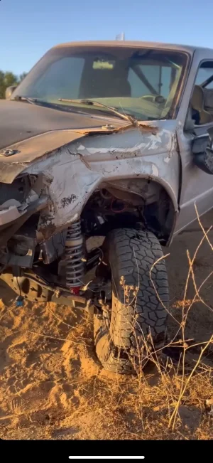
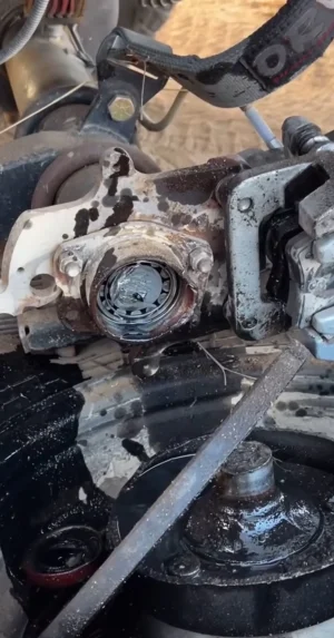
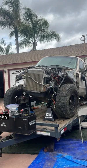
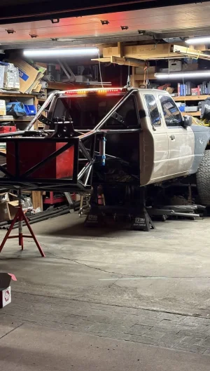
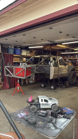
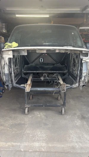
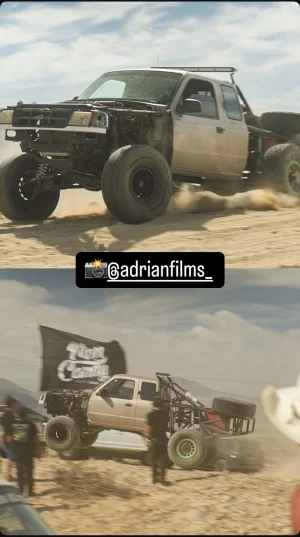
I got a couple good trips in but the front end could not keep up with the rear and kept breaking. Not to mention the lack of power. After the 2025 DSSO in April I decided to chop the front end off and force myself to make something better.

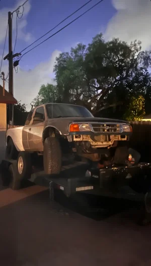
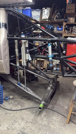
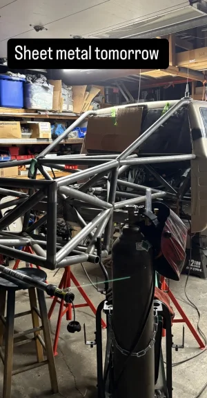
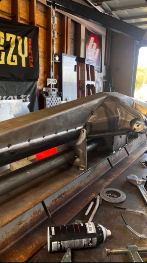
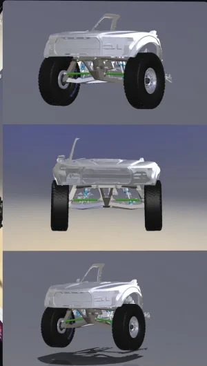
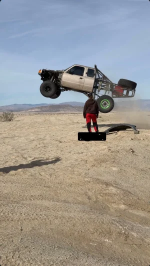
I decided center mount would be a fun project that would challenge my skills. I wanted it to be badass as possible, 4130, tig welded, swing steer, ect. I started with picking up a mcNeil 86" front clip. It was important to me that fiberglass still could fit the truck and it would look completed, but with the Rangers very narrow with its hard to tuck tires that bump out to the windshield so I used a scan to help me find an Ideal track with. Came out to be 87.5", same as the rear. I knew with this front end my priories where to have a nimble driving feel with minimal CPTC and a relatively strong camber curve. However, there's always a downside. While the camber curve did help a bit to tuck the tires in the glass it meant my shocks would have to lean in more making my motor need to get pushed further back. I gained a more progressive shock angle, ideal camber curve and CPTC scrub but I had to move my motor entirely behind the cowl. But hey, rear weight bias right?

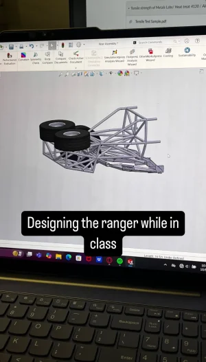
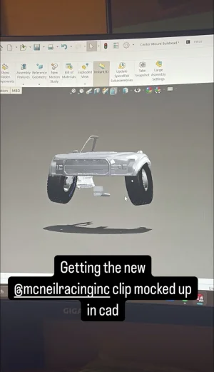
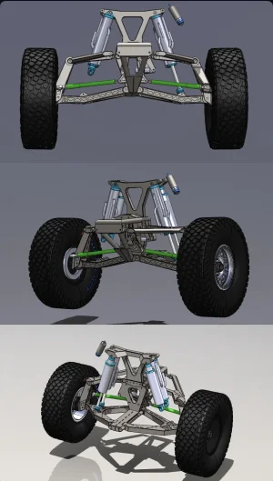
Spent a solid 3 months of my evenings working on the design, most of which was spent getting the geometry for the steering. While swingers are great for having adjustability of the toe curve through out the steering, it takes a considerable amount of work to get it in a good spot. There are a lot of variables that can be modified such as swinger length, top spread, bottom spread, center link height/offset, position front to back, steering arm position all which result in slightly different geometry. I ended up making a spreadsheet to track all the different options and made some formulas to find the most ideal geometry with in my constraints. I filled over 400 rows in excel but it was worth it to get it where I wanted.
 

Attachments

  • IMG_4991.webp
    IMG_4991.webp
    67.7 KB · Views: 17
  • IMG_4990.webp
    IMG_4990.webp
    360.7 KB · Views: 14
  • IMG_4987.webp
    IMG_4987.webp
    106.5 KB · Views: 14
  • IMG_4989.webp
    IMG_4989.webp
    166.9 KB · Views: 18
  • IMG_4986.webp
    IMG_4986.webp
    467 KB · Views: 20
  • IMG_4992.webp
    IMG_4992.webp
    179.9 KB · Views: 20
Back
Top