3RD GEN 4 RUNNER

STUDIO305

Member
Joined
Feb 8, 2024
Messages
20
Hey all, I'm Andrew!

Huge fan of the forum and been watching Wally on YT for many years! - Stoked to see this place active and the general vibes and community its created, definitely nothing like the rest.

With that said, I figured I'd post up some build photos and catalog the changes and fab work done up on a buddies rig from work. It started when he caught wind of some work I'd been doing for some of our house brands (Tuff Stuff and Body Armor 4x4) for Jeep Beach Fest/Overland Expo etc.

From what I was originally told, he bought the rig like this and made only minor changes before he'd decided he wanted to change things up.

From a mix of Amazon parts, Fox and King, to Total Chaos and more, there was a mix of everything and work done to the rig.
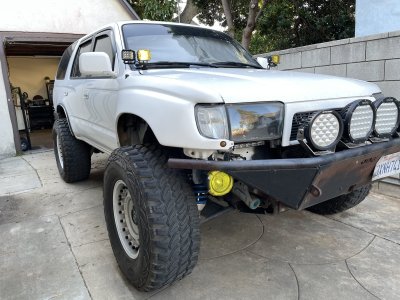
IMG_9243.JPG

IMG_9239.JPG

IMG_1183.JPG

The driver side had a Fox setup and the pass rear had an OEM Pro Comp replacement.
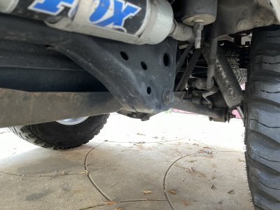
IMG_9236.JPG

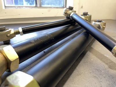
Originally, the idea (and parts that were sent with the rig) was to throw on some new rear links (upper and lower), brace the front coil buckets, add a Solo Motorsports outboard shock setup to the rear, and burn in some link mount bracing and brackets...but that didn't last too long haha.
IMG_9261.JPG

IMG_9256.JPG

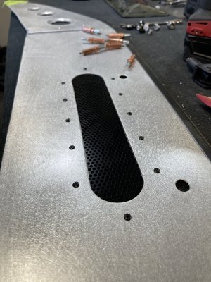
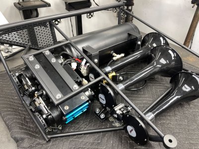
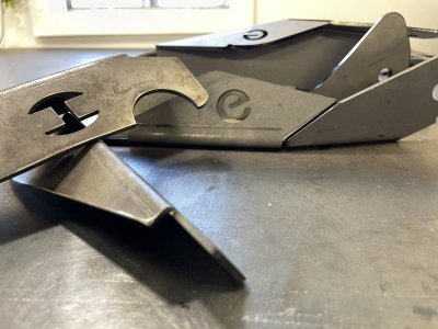
First up was to pull off everything I could and rework the front bumper, clean it up and add some faceplates up front and a trim panel on top. While I had it off, some horns that were mounted up front were just zip-tied on, so they got a mount and proper wire routing.
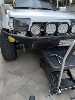
IMG_9263.JPG

IMG_0313.JPG

IMG_0332 2.JPG

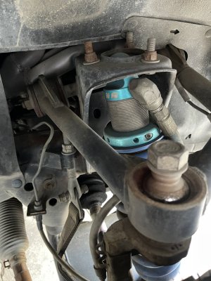
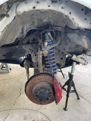
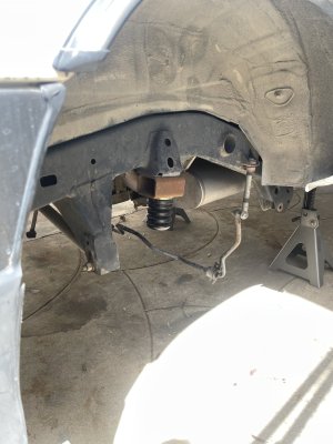
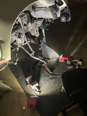
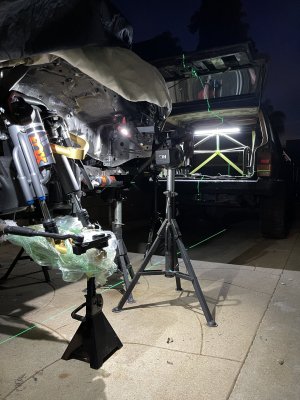
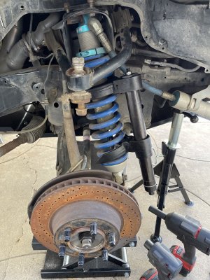
Pulled the front end off - the upper coil mounts main bolt was bent, and the threaded collar was seized up so it was easier to just compress the coil and pull everything out as one.
IMG_1200.JPG

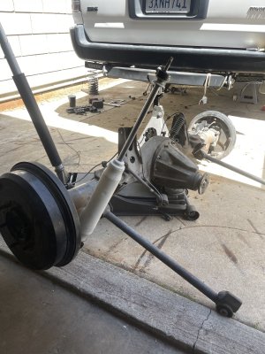
Got the rear end dropped so I could burn in the link reinforcements and while I was at it, start chipping away on each corner - removing the OEM bumps and other bracketry.
IMG_9266.JPG

IMG_9666 2.JPG

IMG_9268.JPG

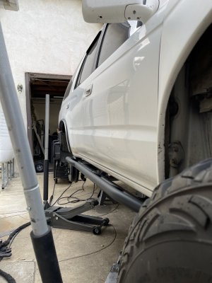
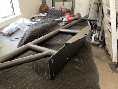
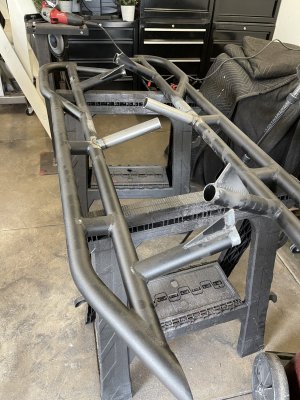
He was very set on utilizing some new gen 4 Runner sliders that we offer - obviously, the mounting plates are much different so I lobbed them off, prepped everything and added more tubes and welded em' up.
IMG_9797.JPG

The center-most tubes were moved to clear under the cab and to also be more symmetrical and inline with the front and rear most standoff.
IMG_9810.JPG

IMG_9815 2.JPG

I'm noticing now A LOT of the photos were taken at different times/stages but I'll try to get them best organized so it's not a back and forth affair.

 
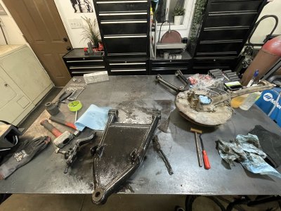
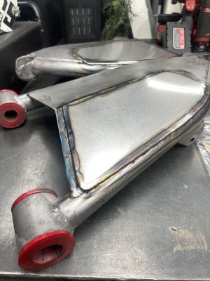
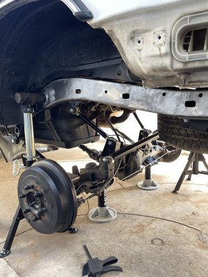
Completely pulled the front end apart so the arms could originally get powder coated, in that lapse of time however, I got them sand blasted, and cleaned them up a bit. I'd added some more plating to the underside, double sheared the mounts and added bump pads to them as well.
IMG_1217 3.JPG

From what I understand, they're Total Chaos uppers/lowers - they had some substantial pitting as well as 'dent's from the tierod, etc binding up against them at full lock/droop.
IMG_1222.JPG

IMG_1251.JPG

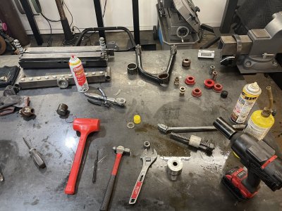
After this nightmare of removing the old uniballs and bushings I got the arms blasted and got to work.
IMG_8141.JPG

IMG_8158.JPG

IMG_8344.JPG

IMG_8633.JPG

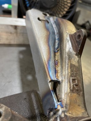
Prepped both uprights and added in some spindle gussets

IMG_1260.JPG

IMG_1265.JPG

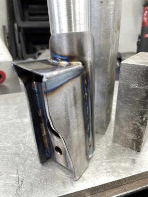
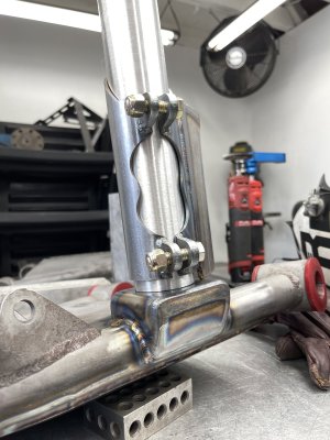
So for the front setup, it was decided to run a coilover/bypass setup so Solo kit was ordered up. No coilover mounts are sold for the 3rd gen so I built up my own - it's definitely my first time dealing with that and a bit cumbersome mounting them to the coil and sliding everything up to bolt into the bucket.
IMG_7797.JPG

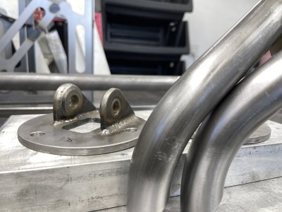
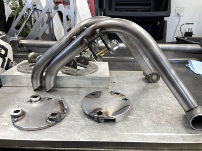
Burned in the shock tabs and decided to weld the standoffs to the top-hat. I added a small tab towards the front so there was an equal amount of mating surfaces (which would be welded to the top of the coil bucket as well).
IMG_7793.JPG

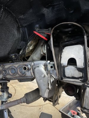
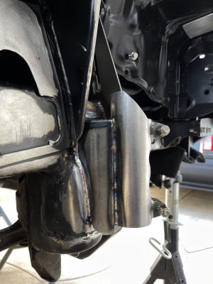
For the lower standoff of the shock 'tower' I opted to weld in an inner sleeve that passes through the frame rail. The standoff of the tower slides over this and everything was welded together. And while everything was apart I cleaned up the frame rails, resprayed the inner fenders and plated off the frame rails (while filling in any open and/or unneeded holes).
IMG_8603.JPG

IMG_7813.JPG

After double passing everything that I could for the time being, I started adding in a lower brace as well.
IMG_8654.JPG
 
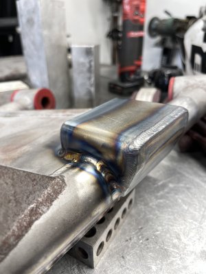
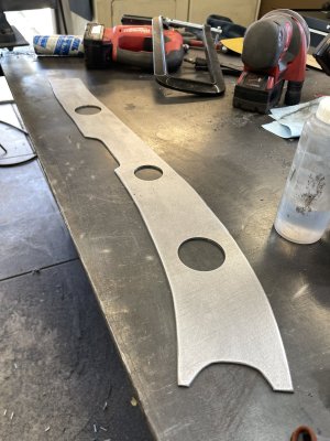
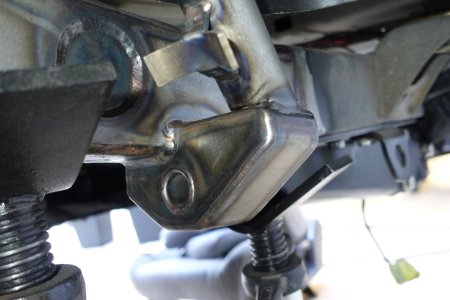
Next up was mounting the bump stops - I opted to trace up the side profile of the frame rail 'hump' where the OEM bumps mount underneath. Drew them up in Fusion after importing a photo of the template and got them cut up. With the leverage applied to the cans with them striking so far into the arm I added some internal bracing to the can mount.
IMG_8628.JPG

IMG_8632.JPG

IMG_8640.JPG

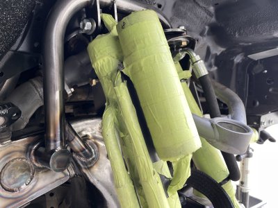
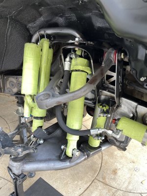
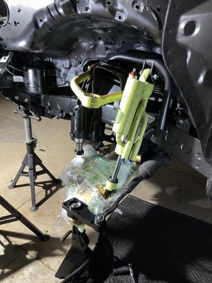
With the Fox shock package in hand, I could finally get to mocking everything up and cycling things while verifying the bump stop contact.
IMG_8672.JPG

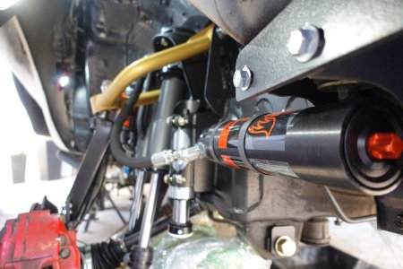
Got resi mounts tabbed in to hang those and added in the Solo shear kit - I added weld washers to the outer most tabs - In turn I had to order some 4th gen upper shock bolts as they're about 20mm longer and would allow for proper thread engagement once slid through the upper and shock tower.
IMG_8668.JPG
 
Last edited:
Awesome work - this is another yota refresh thread - he made it possible to use two bolts for the upper.


Last edited:
Awesome work - this is another yota refresh thread - he made it possible to use two bolts for the upper.


Thanks so much! Thanks for the link to that, found myself scrolling through his hole thread too and love the idea of the two separate bolts up top.

Nice to see more 4r getting built
Where you at?

Appreciate it! Located in So Cal!

right on dude! welcome!

I've had a Tuff Stuff Roof top tent for the last 10 years haha !

DW! Thanks so much! I've definitely seen your rig floating around IG with the tent up top too!
 
Spent the last day organizing all the photos and getting things sorted.

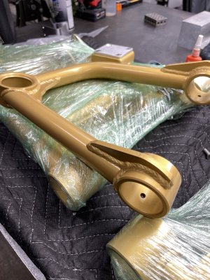
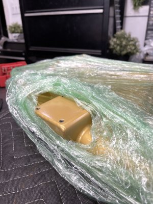
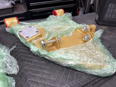
Got the arms back from Cerakote! We'd debated on Steel-it, Powder OR cerakoting the arms and coils.
IMG_9133.JPG

Chased the threads and cleaned up the bump pad mounts so I could get the pads mounted up.
IMG_9136.JPG

All dressed with new bushings and shanked the hardware as well.
IMG_9139.JPG

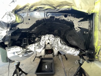
I took the opportunity to clean up the fender wells and get some fresh paint and undercoating on where/as necessary. Using the foil always makes me laugh, but man it can come in super handy versus tape/paper.
IMG_1675.JPG

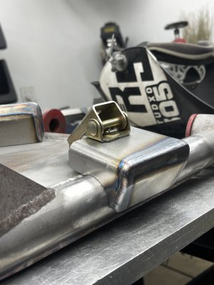
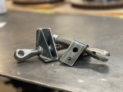
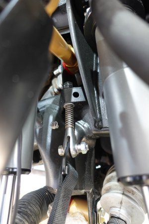
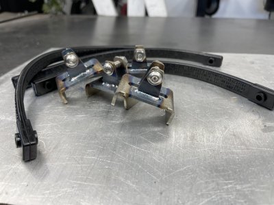
Built up some new limit strap mounts for the adjustable clevis' - the old mounts were some hogged out nuts and some scrap steel tacked on to hold the clevis.
IMG_1398.jpg

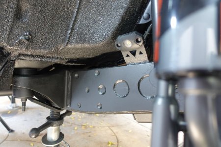
After cleaning up the frame rails and getting them plated, I'd added in some tabs for some rock lights.
DSC00129.JPG

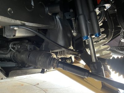
Mocked everything up and started cycling to double check clearance(s) and everything checks out. Got the tie rods cleaned up and installed the TC lower uniball conversion as well.
IMG_9235 (2).JPG

DSC00130.JPG

DSC00132.JPG

IMG_9283.JPG
 
Whipped up some mounts to ziptie to the limit straps and keep them away from the crowded corners at full bump. There's definitely a lot going on - better safe than sorry.
IMG_0773.JPG

IMG_0778.JPG

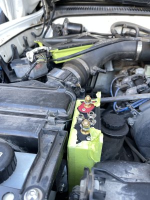
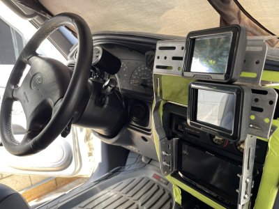
While I was still working up in the front, I started to tackle the mounting location and mounts themselves for the Scosche PDM units. Two touch screens will mount inside for the user interface. These are definitely ginormous compared to a Motec/Switch Pros etc. He was adamant about not mounting them inside or towards the rear, and they needed to be high up for potential water crossing, etc.

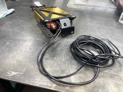
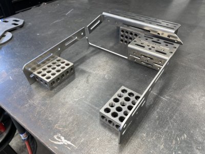
Firstly, I designed up some mounts that the PDMs could mount to, and then started deliberating on where to mount them. Ideally I would have liked to use one mount with both PDMS mounted to, but I had to split them up.
IMG_0511.JPG

I got one of them mounted up over the ABS? system in the passenger corner.
IMG_0547.JPG

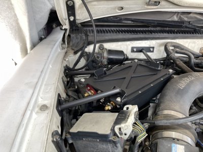
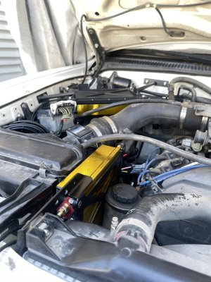
This second one, I was able to snake between the airbox and the power steering reservoir. Had to make some relief cuts in the main bracket, and build two standoffs to hold it securely.
IMG_0577.JPG

I had previously relocated the windshield washer tank to inside the engine bay(in front of the airbox), and was able to utilize two of its mounting holes as well as the upper rad mount to secure this one.
IMG_0579.JPG
 
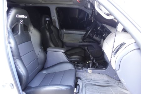
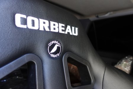
Moving towards the back, I got some new Corbeau seats (and Corbeau brackets) installed.
DSC00053.JPG

DSC00143.JPG

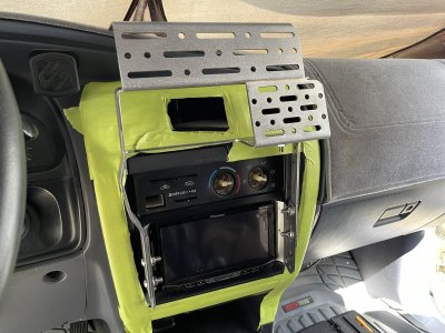
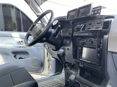
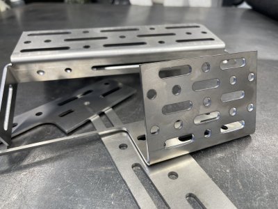
Another request was to build out a molle mount for his accessories inside. No drilling or rivnuts in the dash was also requested. Now there is one mount out there that fits the bill but it mounts down by the radio with (4)sheet metal screws into the plastic trim.

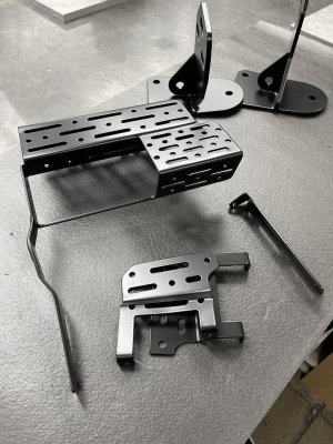
So this is what I drew up and had cut out. Plenty of options for mounting locations and orientations.
IMG_0897.JPG

Due to all the bends and their locations, I had to break it up into a few pieces - This proved beneficial in getting everything mounted as I wanted and keeping the entire assembly close to the radio console and controls.
IMG_0900.JPG

Mocked up in place - still clears the cup holders and you can still see the OEM clock - temporary hardware for now.
IMG_0913.JPG

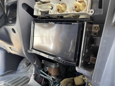
It shares the same mounting holes as the head unit.
IMG_0904.JPG

IMG_0924.JPG

Back from powder - glad I oversized the holes and splines as I was concerned the powder may add to much material and the hardware wouldn't pass through.
IMG_0997.JPG

Used some cap covers from McMaster to try and hide the hardware as best I could. Ideally I would've have cut and welded everything as one unit but I needed it to be adjustable to best suite his needs. It also helped in assembling the system - Mount the brackets to the radio, hold up the trim panel and connect the hazard lights, and usbs and slide it over the mounts, mount the trim panel and assemble the rest of the molle system
IMG_1018.JPG
 
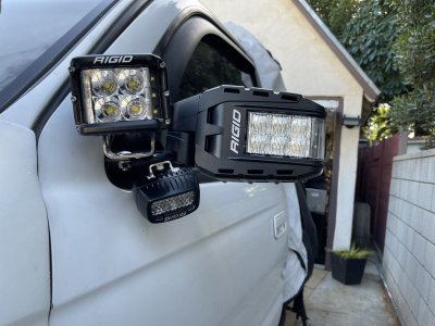
Starting working on some new mirrors for the rig - he wanted to remove the standard ditch light setup utilizing the rear-most hood mounts and get lighting more from the side and less reflecting off the hood.

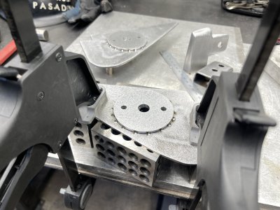
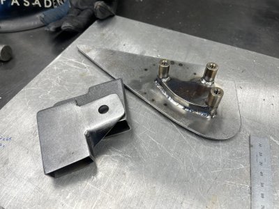
I started out by first removing all of the OEM setup and wiring. I was then able to template out the mirror 'baseplate' and get that cut out. I was given some Rigid reflect Mirrors and some additional lights to hang off the assembly.

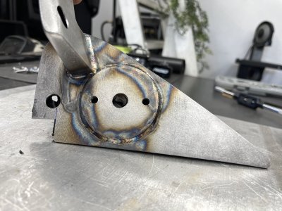
The circular tab is just oversized compared to the Rigid light, and I added some pass-through holes for the wiring as well as the mounting hardware itself.
IMG_0614.JPG

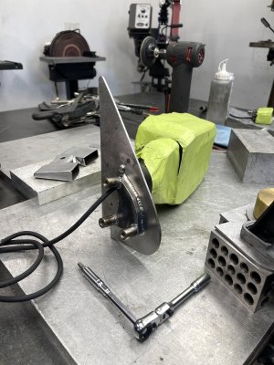
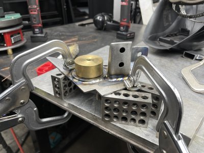
First pass welds on the mounting flange to the back of the baseplate. The 3 standoffs pass through the outer door sill and allow for an OEM mounting fashion from inside.
IMG_0619.JPG

Mocked up and ensuring everything stays flat and true throughout all the welding.
IMG_0623.JPG

Finishing up the welding of the light tabs and the mirror mounting provision.
IMG_0632.JPG

IMG_0668.JPG

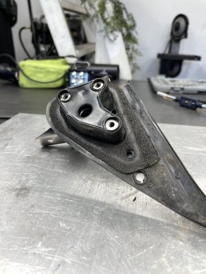
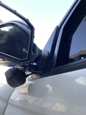
Pretty stoked that I was able to utilize the original weather seal from the stock mirror - added a few new holes for the wiring to pass through and end up inside the door panel for wiring later on down the line.
IMG_0667.JPG

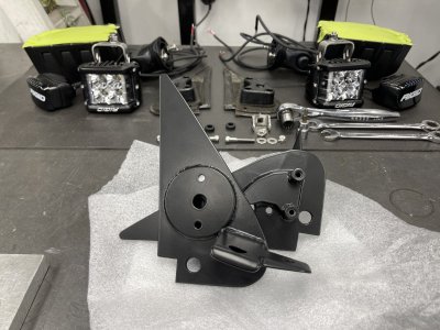
Got everything back from powder and after throwing the weather seals in the ultrasonic cleaner to remove all the dirt and grime, I was good to start final assembly.
IMG_0720.JPG

Mounted up the lights and mirror to the baseplates for good. I did leave the two additional lights just tight enough, but will let him adjust them officially for what best suites him.
IMG_0725.JPG

IMG_0727.JPG
 
Onto the rear end - Started off with cleaning up the frame rails and prepping them for some overlay plates. While I was at it I freshened up the inner fender wells as well.
IMG_2589.JPG

IMG_2592.JPG

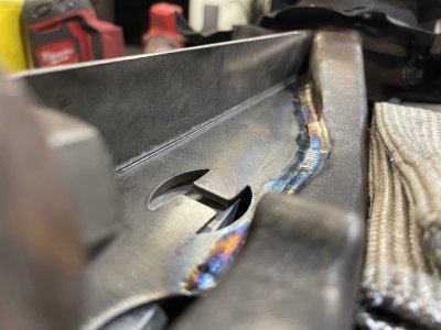
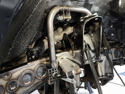
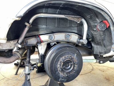
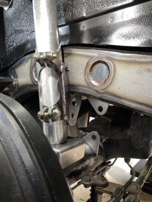
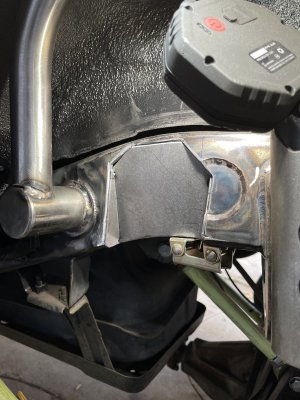
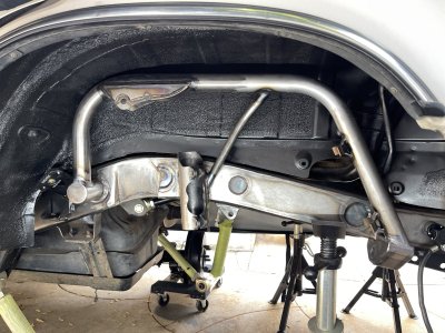
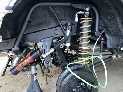
The original plan was to utilize the Solo Outboard Shock mounts, but I wanted to change things up a bit - by way of boxed upper mounts, integrated bracing into the bump mount, and I wanted to weld out the hoops to a center bar that ran through the frame rails with the rear mounting more so with the frame rail rather than off the side.

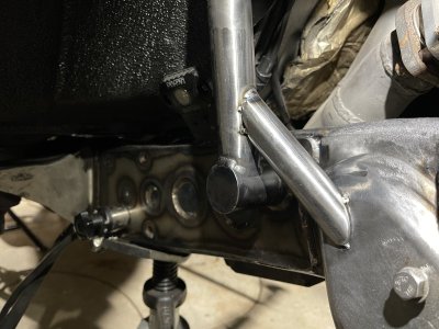
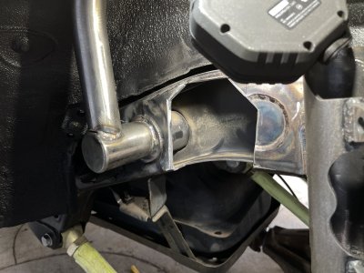
The front mounts through the OEM pass through - first with some Steel-it applied, I passed it through and centered it up. It's 2" .120 4130 and I felt better with this setup rather then the entire hoop hanging off the side(s) of the frame rail. If I was to go into the cabin, I maybe would have kept with that original program and tied both hoops to each other.
Mocking everything up and verifying things clear and that I can also build off the frame rail for the rear mount.
IMG_8752.JPG

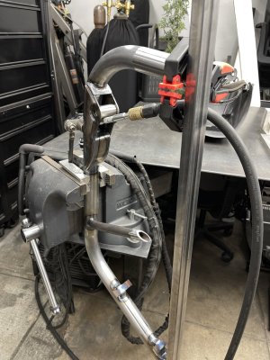
With everything looking good, I braced up the hoops and welded them out.
IMG_8847.JPG

Knowing that we were going with an outboard coil setup, I next notched out the frame rail.
IMG_9403.JPG

Built out some bump can mounts and got them welded out and then tacked into place.
IMG_8828.JPG

Roughing out the fitment of the inlay plates to close in the notch.
IMG_9405.JPG

DSC00094.JPG

IMG_0109.JPG

DSC00067.JPG

DSC00077.JPG

The last bit was assembly and some fresh paint. I also added in an onboard air system for refilling the tires, etc. and got the Schrader valves integrated into the rock light tabs that I previously added throughout the chassis.
IMG_0399.JPG
 
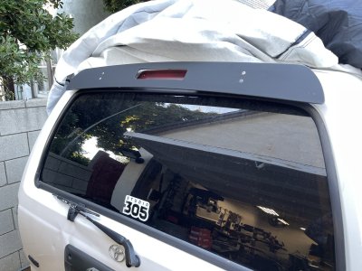
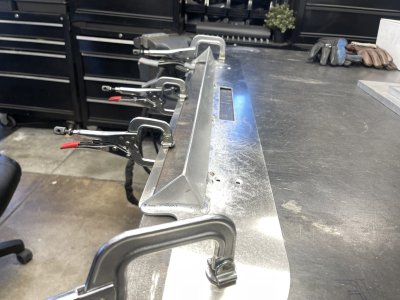
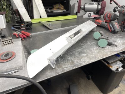
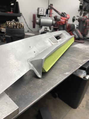
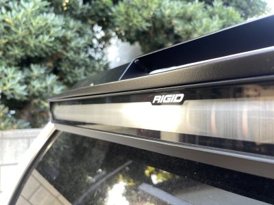
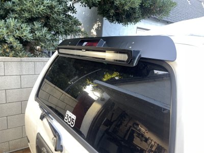
With the shipment of Rigid lights, was also a chase bar for the rear 'spoiler'. He wanted to integrate the two - the Chase Bar and spoiler, while still retaining the 3rd brake light up top. Similarly to a Snowbound customs spoiler that uses some Baja Designs lights mounted toward the outer edges of the spoiler.
IMG_9983.JPG

Got some strategic wins in while welding this out and ultimately got it to contour in the same way the OEM one does.
IMG_0042.JPG

Built some tabs off the back of it to hang the light from and still allow it to adjust up/down.
IMG_0094.JPG

I opted to add in some corners as well, as the light has some pretty steep angles on it and the gap present in the corners looked a bit out of place.
IMG_0096.JPG

In finishing it up, I added the same corners to the underside and ran a strip along the underside to tie things in visually and to add additional support from side to side.
IMG_0480.JPG
 

Attachments

  • IMG_0476.JPG
    IMG_0476.JPG
    320.8 KB · Views: 7
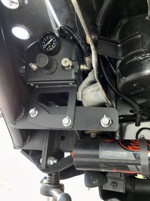
Started chipping away at the air controller and mounting it. I originally thought this could work out pretty trick, but would then realize you couldn't easily read the dial or access the schrader valve(s).
IMG_0338.JPG

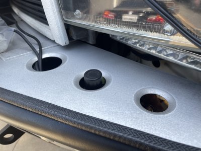
Opted to install it just underneath the bumper bezel. With it being here, it's super easy to read, set the pressure and access the other features.
IMG_0499.JPG

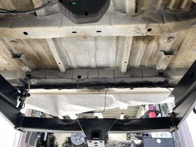
Next up was removing the rear tire and hanger assembly - Got things tidied up a bit in regards to wiring and what not.
IMG_9935.JPG

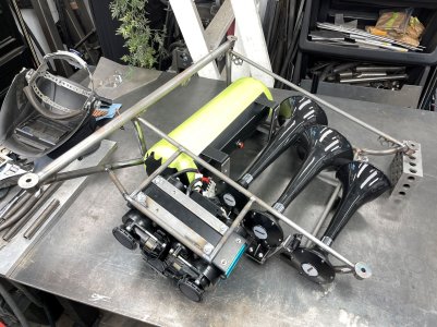
Packaging all of this proved to be a bit 'much'. The parts I was given were much different than previously discussed (I'd already started building out the tube structure so it's ultimately my learning mistake), so I had to adapt and change things up a bit. Regardless, all good, got the horns, tank, and compressor mounted up.
IMG_0326.JPG

Added some paint, dzus tabs and some expanded material in the back.
IMG_0431.JPG

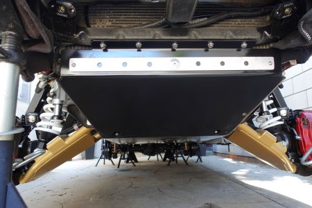
Front to rear skid plates are done and sorted. They keyway into each other and ends just before the gas tank. I added a small kicker on the passenger rear side to cover a majority of the muffler (dimple died throughout to prevent any heat soak). Also got the Revolve lights mounted on the uprights.
DSC00161.JPG

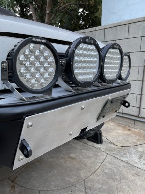
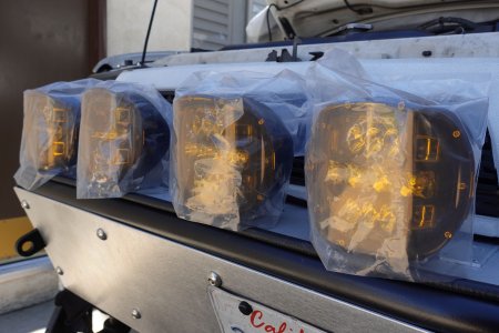
Tossed out the old ProComp's and mounted up some new Rigids.
DSC00169.JPG
 
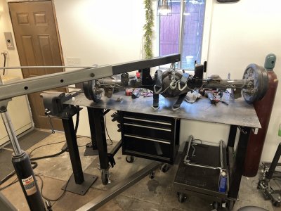
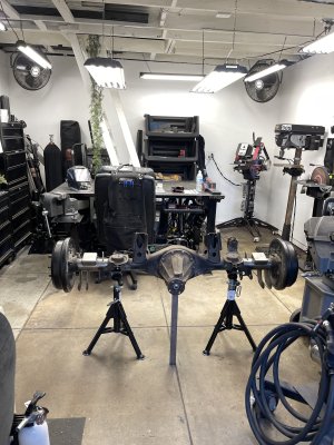
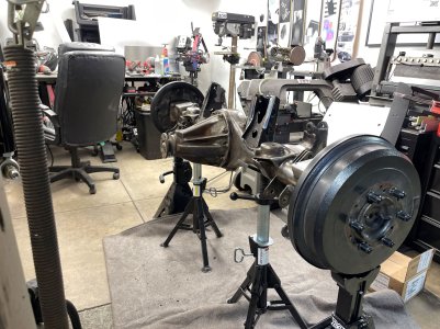
With the axle removed, I could start tabbing it out and working on the skid plate for it as well. Shock mounts, bump pads, bracing, and limit strap mounts were only tacked on for cycling, etc.
IMG_9530.JPG

I started by first going through some past work and cleaning things up, wire-wheeling and DAing a lot of the axle too.
IMG_9550.JPG

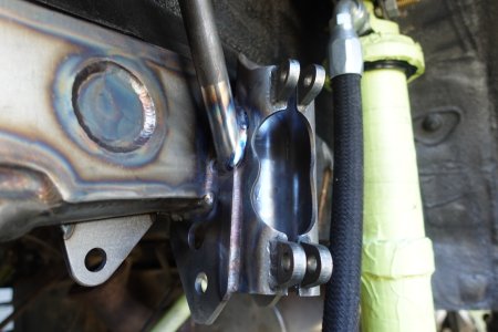
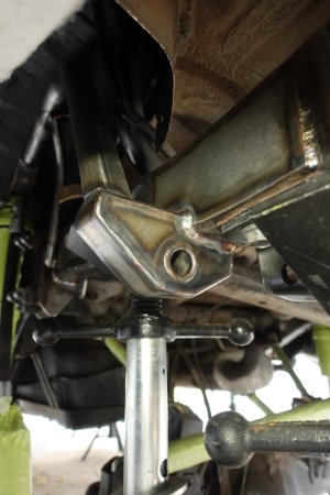
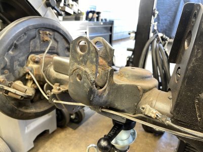
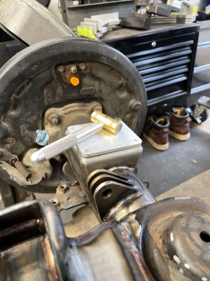
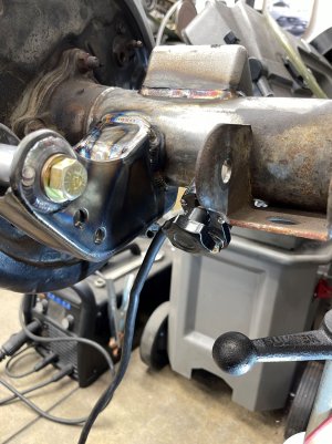
Braced up and repaired as best I could the panhard bar mount - I opted to plate in the front portion (that leads to the coil bucket), as well as the mount itself - fully boxing it in, and added weld washers as well.
IMG_9633.JPG

Burned in the limit strap tabs.
IMG_9653.JPG

I gave the rear axle the same bump pad treatment as the front arms. Threaded the mounts and welded them out and cut up some pads to mount atop.
IMG_9665.JPG

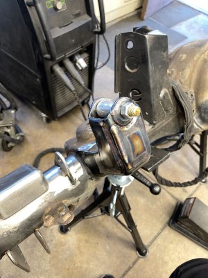
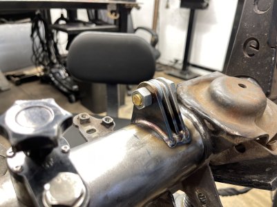
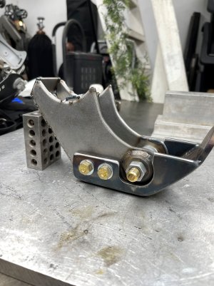
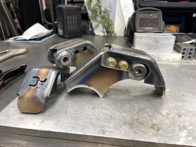
The rear shock mounts were from a friend of his, and cut out on a plasma table. It took a lot of work to get these things cleaned up and aligned, but it worked out. I opted to run weld washers, box in the backside as well as through the front.
IMG_9679.JPG

Fully welded out and ready to mount up to the axle.
IMG_9699.JPG

I can't find the picture, but I ended up tying in the lower link mount and the shock mount together (basically where the welders ground is).
IMG_9885.JPG

Got everything cleaned up, wire wheeled entirely, and reassembled, and ready for some paint.
IMG_0027.JPG
 
Back
Top