5. Shackle Hanger Location
Overview:
Shackle hanger location is largely application-specific and depends on both spring geometry and suspension travel goals. The correct location ensures full bump and droop travel without binding, interference, or inversion while maintaining consistent rate behavior through the stroke.
Compression-Style Systems
For compression-style shackles, the primary goal is to prevent shackle inversion and maintain predictable ride quality.
A widely used baseline formula for locating the hanger is:
Hanger Spacing = (Spring Flat Length) − (Shackle Length) + ½″
(½″ accounts for bushing deflection under load.)
This provides a starting point, not a final dimension. Each vehicle’s frame geometry, spring arch, and shackle length will require small adjustments to achieve proper clearance and geometry.
Important Note — Tension-Style Shackles
The above formula is derived from compression-style geometry, where the shackle hangs down from the frame and pushes on the spring eye, often with the upper mount forward of the rear spring eye on the frame.
That math assumes:
- The shackle pivot is above the spring eye.
- The shackle swings rearward as the spring flattens in bump.
In a tension-style system, the opposite is true:
- The shackle is located below and behind the spring eye.
- It pulls on the spring eye as the spring compresses.
If you apply the compression-style formula to a tension setup, the calculated hanger position will land too far forward on the chassis, placing it under the leaf pack instead of behind it.
This creates several problems:
- Immediate interference at full droop, where the spring eye and shackle swing into the hanger.
- Severely limited downtravel and premature shackle binding.
- Unintended rate change due to incorrect geometry (a secondary concern compared to clearance loss).
Correct Method — Mock-Up and Scribe-Arc Placement
For tension-style shackles, the hanger location must be determined by physically cycling the suspension and plotting the path of the spring eye.
Procedure:
- Set the vehicle at ride height
- With the suspension set for mockup with the stripped main leaf, set the suspension at ride height
- Install the shackle to the spring eye and hold it at the desired angle.
- Establish the neutral shackle angle
- The shackle should usually sit perpendicular (90°) to the spring’s eye-to-eye datum line at ride height.
- Avoid any rearward lean at ride height — this stiffens the effective rate too early and can cause rough ride and poor handling..
- Check full bump
- Cycle the axle to full bump (spring near flat).
- Ensure the shackle is not forced into a flat or locked position that binds the spring or over-loads the bushings.
- If binding occurs, verify shackle length — a shackle that’s too short can cause premature lock-up.
- Check full droop
- Let the axle droop completely.
- Confirm that the shackle and spring eye clear the hanger, frame rail, and spring pack with no hard contact.
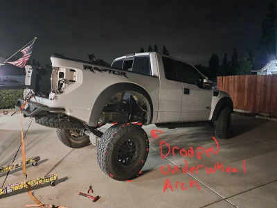
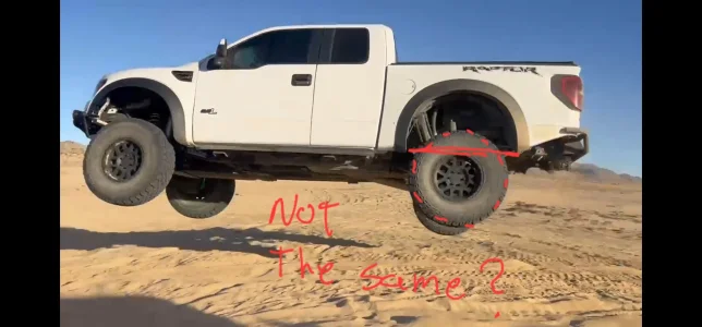
- Droop clearance, not bump clearance, is usually the limiting factor in a tension setup when finding the hanger location
- Mark and verify the final hanger position
- Tack-weld or secure the hanger in the verified location after both bump and droop clearances have been confirmed.
- Re-cycle the suspension to double-check all clearances before final welding, bolting, etc.
Weight Consideration
Vehicle weight has a direct influence on ride-height geometry. Heavier vehicles compress the spring’s free arch more at static ride height, changing the effective shackle angle.
Always confirm the final hanger position with the full vehicle weight installed, not on an unloaded chassis.
Key Takeaways
- Compression-style: use the spacing formula as a baseline, then fine-tune.
- Tension-style: determine location through mock-up and scribed travel arcs.
- Droop clearance, not bump clearance, usually defines the usable hanger position.
- Verify geometry under real vehicle weight before finalizing.
6. Bumpstops and Limit Straps
Purpose:
To protect suspension components and maintain predictable performance by controlling the limits of compression (bump) and extension (droop). Proper bumpstop and limit-strap setup prevents over-extension, harsh bottoming, and premature wear of shocks and springs.
Bumpstops
Function:
Bumpstops act as the suspension’s final line of defense during compression, absorbing and decelerating the last portion of travel to prevent hard contact between the axle, frame, and shock internals.
Types and Behavior:
- Polyurethane or Rubber Bumpstops:
Common in OEM applications. These compress almost completely flat under load, offering limited tunability but low cost and simplicity.
- Hydraulic Bumpstops:
Use a nitrogen-charged chamber and internal valving to slow the axle progressively near the end of its stroke. Highly tunable and rebuildable for performance use.
Setup Guidelines:
- Polyurethane / Rubber:
- Assume full compression to a flat state.
- Mount the bump pad on the axle so the stop contacts flush at full bump.
- Hydraulic:
- Remove the Delrin pad from the bumpstop before setting the pad height.
- Collapse the bump completely against the axle pad to establish its true compressed height.
- This accounts for pad wear and possible nitrogen pressure loss over time.
- Shock Clearance:
- At full bump, ensure at least ⅛″–½″ of shock shaft remains visible to prevent internal piston or seal damage.
- For bypass or coilover shocks, confirm that secondary zones or stops are not engaged prematurely.
Limit Straps
Function:
Limit straps prevent the suspension from over-extending at full droop, protecting shocks, springs, and driveline joints from damage.
Setup Guidelines:
- Measurement:
- Measure the required strap length with the axle at full droop and the shocks 1″ short of full extension at least.
- This ensures the strap, not the shock, controls maximum droop.
- Stretch Allowance:
- Fabric straps typically stretch up to 1″ over their service life.
- Compensate for this by using adjustable clevis mounts and setting initial strap length accordingly.
- Installation Tip:
- Recheck strap length after the first few cycles; early stretch is normal.
- Maintain at least 1″ of shaft inside the shock body at full droop.
Key Takeaways
- Proper bumpstop and limit-strap setup ensures reliable, repeatable suspension performance.
- Always leave at least ⅛″–½″ of shock shaft at bump and ≈1″ at droop.
- Cycle the suspension through full travel after setup to confirm no interference or premature engagement.
8. Shock Absorber Setup
Purpose:
To correctly locate and set up shock absorbers for maximum control, reliability, and suspension efficiency within a leaf-spring system.
Shock Selection
To achieve consistent damping and tuning capability, it’s recommended to use a universal-style performance shock—typically rebuildable and externally tuneable (bypass, coilover, or smooth-body).
These shocks allow precise adjustment of compression and rebound characteristics to match vehicle weight, spring rate, and terrain.
Mounting Guidelines
- Set at Full Bump:
- Position the axle at full bump (with bumpstops engaged or mocked).
- Mount the shock so that ⅛″–½″ of shaft remains visible at full compression.
- This ensures the shock reaches full stroke without bottoming internally and prevents seal or piston damage.
- Shock Angle:
- For optimum damping efficiency, aim to position the shock as close to 90° to the axle as packaging allows.
- Angles up to 14° off vertical are acceptable with minimal performance loss.
- Excessive lean reduces effective damping and increases lateral loading on bushings and shafts.
- Mount Clearance:
- Verify that both upper and lower mounts provide sufficient clearance from the frame, tires, leaf pack, and any crossmembers.
- At full articulation, the shock body and reservoir should not contact the spring, hanger, or shackle.
- Cycle and Verify:
- After initial mock-up, cycle the entire suspension from full bump to full droop.
- Check for any binding, interference, or shock body contact.
- Confirm that bumpstops engage before the shock bottoms and limit straps engage before it tops out.
Key Takeaways
- Always mount shocks based on full bump position, not ride height.
- Maintain ⅛″–½″ of shaft at bump and ≈1″ inside the body at droop.
- Keep the shock near 90° to the axle for maximum damping efficiency.
- Cycle the suspension to verify clearances and stop sequencing before final welding.


