Dtc81
Member
- Joined
- Feb 19, 2025
- Messages
- 17
Yep. It's a mail truck! A Grumman LLV if you wanna get technical...This is going to be my best attempt to build my "dream" truck. I have always wanted to turn one into a quirky "do-it-all" unit. Something that can hold its own on the rocks, be safe and capable at speed, go down the road straight, and haul the family for short fun runs.
Current Parts Spec:
Engine: GM LQ4 6.0L
Trans: 4L80e
T-Case: Ford NP205 with ORD Magnum Underdrive
Front Axle: 2015 D60 with MoFab keyed high steer arms, Barnes truss
Rear Axle: Sterling 10.5 with Artec truss
Wheel/Tire: Sidetracked Off Road 17" forged bead locks, 40" KR3
Goals:
-Push my design, fabrication, and welding skills.
-Retain LLV charm: sliding doors, rear roll up door, general proportions, basic amenities.
-Have a little bit of race car vibe.
-Low CG, ideally flat bottom the whole thing. It's going to drag.
-Safe.
Backstory:
I spent nearly 6 years trying to track down a mail truck, and finally scored this one in 2022. I tried buying this LLV in 2019 when the owner was in Colorado, but he decided to keep it. Two years later I missed a FB message from him while I was at Fabtech. He sold it the next day. I found another, much cleaner LLV in Maryland, but the owner wanted a ton of money for it. He sold it, but the buyer mentioned he had an LLV in rough shape. We got in contact, both had wives due with kids any day, so tabled the sale until the newborn dust settled a few weeks later. After a 19 hour driving day I finally had my LLV.
Well, life took over for a few years, so it sat behind the barn while we were building a new shop. I was slowly buying drivetrain parts as I found them. I work in construction, and have a small welding and fabrication business on the side. (@dcbuiltllc on Instagram for those curious). This is by far the most extensive vehicle fab project I've done, so I'd love any criticism and feedback! I've been following a bunch of different social media accounts, YouTube channels, and forums for years now, trying to soak up as much knowledge as I can.
I started by building a simple chassis table out of some channel, and then dove into stripping the LLV. I knew I wanted to challenge myself with a full chassis build, so only the body was saved. I had a 2000 Chevy Suburban for a motor/trans donor. Stripped that, and kept all the misc./wiring, although I'm leaning towards a Holley Terminator or similar. I tore down the axles so I could properly pre/post heat them during the truss install. I rebuilt and repainted the NP205 and mated the ORD Magnum to it.
Current State:
As of this post (1/1/26), the body is on stands. The motor and trans are roughed out onto the chassis table, and the front axle is positioned. I need to cut some of the floor/firewall to drop the body lower, and further back.
I have some questions; hopefully people can drop some knowledge!
1) Is there an "ideal" starting location for the engine relative to front axle? Currently cylinder #1 is 6" behind the front axle centerline. I'd like to centralize the weight, but not to the point where the "step van" vibe is completely ruined by a big engine/trans tunnel. Driveline length is also a consideration.
2) Current plan is to mock up at full bump to see packaging/layout constraints. Layout linkage design and then work it to ride height. I have archived a bunch of old forum posts and online calculators to help guide me. Does this sound reasonable?
3) Is there a general rule for how much clearance should be between engine and axle at full bump? (Just a starting point number). Currently around 2" as is.
4) I'm open for options on suspension design - at a minimum, basic 4 link rear, but possibly trailing arms because they look fun to build. Probably 3 link front due to space. Plan to run a single 14-16"coil over at each corner. Would love to find more geometry and design info to add to my research if anyone has recommendations.
I've quickly learned this whole thing is a game of compromises! I'm enjoying the learning curve and know there will be lots of tack, test, cut, repeat in my future.
Photo Dump:


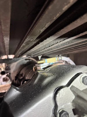
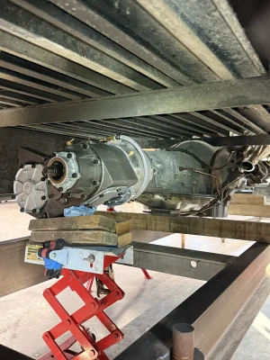
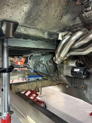
NP205 with ORD Magnum:

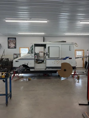
Sliding chassis table under body:

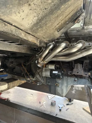
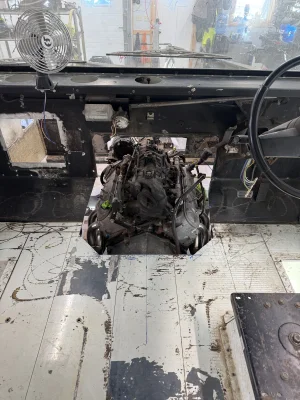
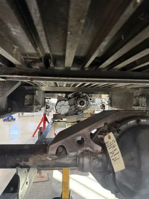
Engine location in relation to front axle:

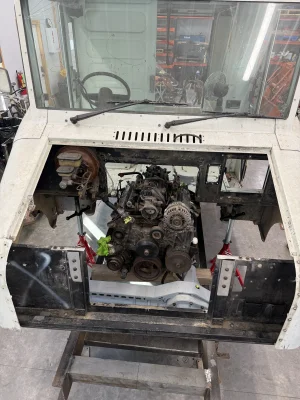
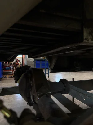
116" Wheelbase for reference:

Current Parts Spec:
Engine: GM LQ4 6.0L
Trans: 4L80e
T-Case: Ford NP205 with ORD Magnum Underdrive
Front Axle: 2015 D60 with MoFab keyed high steer arms, Barnes truss
Rear Axle: Sterling 10.5 with Artec truss
Wheel/Tire: Sidetracked Off Road 17" forged bead locks, 40" KR3
Goals:
-Push my design, fabrication, and welding skills.
-Retain LLV charm: sliding doors, rear roll up door, general proportions, basic amenities.
-Have a little bit of race car vibe.
-Low CG, ideally flat bottom the whole thing. It's going to drag.
-Safe.
Backstory:
I spent nearly 6 years trying to track down a mail truck, and finally scored this one in 2022. I tried buying this LLV in 2019 when the owner was in Colorado, but he decided to keep it. Two years later I missed a FB message from him while I was at Fabtech. He sold it the next day. I found another, much cleaner LLV in Maryland, but the owner wanted a ton of money for it. He sold it, but the buyer mentioned he had an LLV in rough shape. We got in contact, both had wives due with kids any day, so tabled the sale until the newborn dust settled a few weeks later. After a 19 hour driving day I finally had my LLV.
Well, life took over for a few years, so it sat behind the barn while we were building a new shop. I was slowly buying drivetrain parts as I found them. I work in construction, and have a small welding and fabrication business on the side. (@dcbuiltllc on Instagram for those curious). This is by far the most extensive vehicle fab project I've done, so I'd love any criticism and feedback! I've been following a bunch of different social media accounts, YouTube channels, and forums for years now, trying to soak up as much knowledge as I can.
I started by building a simple chassis table out of some channel, and then dove into stripping the LLV. I knew I wanted to challenge myself with a full chassis build, so only the body was saved. I had a 2000 Chevy Suburban for a motor/trans donor. Stripped that, and kept all the misc./wiring, although I'm leaning towards a Holley Terminator or similar. I tore down the axles so I could properly pre/post heat them during the truss install. I rebuilt and repainted the NP205 and mated the ORD Magnum to it.
Current State:
As of this post (1/1/26), the body is on stands. The motor and trans are roughed out onto the chassis table, and the front axle is positioned. I need to cut some of the floor/firewall to drop the body lower, and further back.
I have some questions; hopefully people can drop some knowledge!
1) Is there an "ideal" starting location for the engine relative to front axle? Currently cylinder #1 is 6" behind the front axle centerline. I'd like to centralize the weight, but not to the point where the "step van" vibe is completely ruined by a big engine/trans tunnel. Driveline length is also a consideration.
2) Current plan is to mock up at full bump to see packaging/layout constraints. Layout linkage design and then work it to ride height. I have archived a bunch of old forum posts and online calculators to help guide me. Does this sound reasonable?
3) Is there a general rule for how much clearance should be between engine and axle at full bump? (Just a starting point number). Currently around 2" as is.
4) I'm open for options on suspension design - at a minimum, basic 4 link rear, but possibly trailing arms because they look fun to build. Probably 3 link front due to space. Plan to run a single 14-16"coil over at each corner. Would love to find more geometry and design info to add to my research if anyone has recommendations.
I've quickly learned this whole thing is a game of compromises! I'm enjoying the learning curve and know there will be lots of tack, test, cut, repeat in my future.
Photo Dump:
NP205 with ORD Magnum:
Sliding chassis table under body:
Engine location in relation to front axle:
116" Wheelbase for reference: